Aircraft Configuration FilesOverviewThe aircraft configuration file (aircraft.cfg) represents the highest level of organization within an aircraft container. Each aircraft has its own configuration file located in its container (aircraft folder). For example, the Diamond DA42 aircraft.cfg can be found at
SimObjects\Aircraft\Diamond_DA42\aircraft.cfg
The aircraft.cfg file specifies the versions of the aircraft included in the aircraft container, as well as the attributes (name, color, sound, panels, gauges, and so on) for each aircraft and where to find the files that define those attributes. Within the aircraft.cfg file there are a number of sections. Brackets enclosing the section name identify the various sections. In order for the simulation to make proper use of any variable, it is important that the variable be located in the correct section. While exactspelling is important, none of the terms are case-sensitive.
See Also
TestingChanges to the aircraft.cfg fileTo see the effects of a change, the flight must be restarted, either by backing out to the UI or by closing Flight Sim World and starting the flight again. Any errors made in creating or editing the aircraft.cfg file will showup, along with the following error messages, while an aircraft is beingloaded. The error messages are listed in order; that is, the firsterror message represents an error early in the aircraft-loading process. | Error Message | Description | | Aircraftinitialization failure. | Indicatesthat some essential files are missing from the aircraftcontainer. If the files are missing, the aircraft will not usually bedisplayed in the Aircraft Selection Screen; as a result, this error israre. | | Failedto start up the flight model. | The.air file was not loaded successfully. | | Thisis not a Flight Simulator aircraft model. | Thevisual model (.mdl) file for this aircraft is not compatible with Flight Sim World | | Visualmodel could not be displayed. | Anerror occurred while loading the visual model (.mdl) file. |
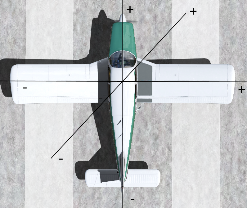
Datum Reference Point | Positions of aircraft components are given relative to the datum reference point for the aircraft, in the order: longitudinal, lateral, vertical. The convention for positions is positive equals forward, to the right, and vertically upward. Units are in feet. The datum reference point itself is specified in the weight_and_balance section. |
Sections of the Configuration File
New and Changed for Flight Sim WorldThe following sections contain and newly added, changed or removed items for Flight Sim World. They are also included in the main body of the document with a red text highlight. [fltsim.n]Property | Description | Examples | | atc_id_color | This is the colour which will be used to render the tail number. This is a hexadecimal number using ARGB format. | E.g atc_id_color=0xFF0FF00 for pure green. | | atc_id_font | This is the font name used for rendering the tail number. The font name must correspond to an entry in Fonts/fonts.json file. | atc_id_font="ARIAL BLACK" | | atc_id_render_target_width | This is the width of the render target which will be created to render the tail number. Note that AI aircraft will have this size divided by 2 (e.g. 512) | atc_id_render_target_width=1024 | | ui_thumbnailfile | Path to the livery specific image to display as a thumbnail in the UI. 600x240 as PNG or JPEG. | ui_thumbnailfile="texture.1\thumbnail.png" | | ui_hangarfile | Path to the livery specific image to display when the livery is selected in the livery selection screen. 1920x1080 as PNG or JPEG. | ui_hangarfile="texture.1\hangar.png" | | ui_selectionfile | Path to the livery specific image to display as the background in the hangar when the aircraft is hovered over. 1920x1080 as PNG or JPEG. | ui_selectionfile="texture.1\selection.png" | | ui_tilefile | Path to the livery specific image to display on the flight planner tile when the aircraft is selected. 210x44 as PNG or JPEG or the Hangar File can be reused here. | ui_tilefile="texture.1\hangar.png" | | ui_visible | If this livery (not aircraft) is visible in the UI. Useful for hiding liveries only used for AI or missions. | ui_visible=TRUE
ui_visible=FALSE | | description | Removed | | | visual_damage | Removed | | | prop_anim_ratio | Removed | |
Property | Description | Examples | | ai_selection_bias | This should always be 0.0 | ai_selection_bias=0.0 | | editable | Removed | | | performance | Removed | |
Property | Description | Examples | station_load.0
to
station_load.n | Specifies the weight and position of passengers or payload at a station specified with a unique number, station_load.N. Parameters in order are: active, Filled Weight (lbs), Max Weight (lbs),longitudinal, lateral, vertical positions from datum (feet), passenger index. Where long, lat and vertical positions are relative to the datum reference point. The addition of stations results in a corresponding change in aircraft flight dynamics due to the change of the total weight and moments of inertia. Active states if the payload has its filled weight by default before the payload amounts are adjusted. Usually Pilot (potentially also copilot) and some Baggage would be active by default on a GA aircraft.
For the passenger index the numbers are as follows:
-1 = Not a person (baggage etc)
0 = Pilot
1, 2 ,3 etc = Passengers, matching with those specified in the model.cfg for the aircraft. | station_load.0 = 1, 190, 350, -0.33, -0.90, 1.29, 0
station_load.3 = 0, 170, 350, -3.05, 0.90, 1.21, 3
station_load.5 = 1, 50,100, -4.54, -0.69, 0.42, -1 | station_name.0
to
station_name.n | This field is the string name that is used in the Payload dialog (15 character limit). Omission of this will result in a generic station name being used. Note that if passed a translation string e.g @IDS_ST_PILOT only the string ID is limited to 15 characters not the translated result. | station_name.0 = "Payload"
station_name.1 = "@IDS_ST_PILOT"
station_name.0 = "Pilot"
station_name.7 = "Forward Baggage" |
[UI Strings] This section is newly added and contains strings which are used within the User Interface, mostly on the Aircraft Selection screen.
Property | Description | Examples | | engine_desc | A short description of the engine of the aircraft. This should fit on one line under the "Engine" heading on the aircraft selection screen. It can be a translation string if required (@IDS_SOMETHING). | engine_desc = "Lycoming IO-360-M1A 180hp @ 2700 rpm" | | prop_desc | A short description of the propeller (if applicable) for the aircraft. This should fit on one line under the "Propeller" heading on the aircraft selection screen. It can be a translation string if required (@IDS_SOMETHING). If not applicable for an aircraft use "--". | prop_desc ="MT 3 blade, constant speed" | | crew_pass | A string for the amount of crew and passengers the aircraft can have. E.g "1+3, 2+2" for the DA42 which can have 1 crew (pilot) and 3 passengers or 2 crew (pilot+copilot) and 2 passengers. | crew_pass="1+1" | | short_desc | A short description of the aircraft to be displayed when the aircraft is selected on the flight planner tile. Should be only a few words, e.g "Innovative, state-of-the-art design" or "Popular two-seat, single-engine monoplane". Can be a translation string (@IDS_SOMETHING) if required. | short_desc="@IDS_SHORT_DESC_RV7A"
short_desc="Popular two-seat, single-engine monoplane" |
[Other Reference] This section is newly added and contains reference speeds and distances used in the aircraft specification panel on the aircraft selection screen. Property | Description | Examples | | range | Estimated range of the aircraft in nautical miles. This is just for reference on the aircraft selection screen, it will not be used in any flight dynamics calculations. | range = 695 | | rate_of_climb | Estimated rate of climb in feet per minute. This is just for reference on the aircraft selection screen, it will not be used in any flight dynamics calculations. | rate_of_climb = 831 | | takeoff_distance | Estimated takeoff distance over a 50ft obstacle, in feet. This is just for reference on the aircraft selection screen, it will not be used in any flight dynamics calculations. | takeoff_distance = 1600 | | landing_distance | Estimated landing distance over a 50ft obstacle, in feet. This is just for reference on the aircraft selection screen, it will not be used in any flight dynamics calculations. | landing_distance = 1525 | | ceiling | Estimated service ceiling of the aircraft, in feet. This is just for reference on the aircraft selection screen, it will not be used in any flight dynamics calculations. | ceiling = 18000 | | fuel_capacity | Reference fuel capacity of the aircraft, in US gallons. This is just for reference on the aircraft selection screen, it will not be used in any flight dynamics calculations. | fuel_capacity = 79.4 | | fuel_consumption_at_cruise | Estimated fuel consumption at cruise of the aircraft, in US Gallons Per Hour. This is just for reference on the aircraft selection screen, it will not be used in any flight dynamics calculations. | fuel_consumption_at_cruise = 13 |
[Accufeel] This section is newly added and contains parameters to adjust the impact of Accufeel on the aircraft. It allows each aircraft to be tuned with custom parameters for Accufeel. Property | Description | Examples | | AccufeelOn | Master on/off for Accufeel on the aircraft. | AccuFeelOn = 1 | | MasterVolume | Master volume of Accufeel for this aircraft. | MasterVolume = 75 | | GlobalTurbulenceStrength | | GlobalTurbulenceStrength = 50 | | GlobalTurbulenceVolume | | GlobalTurbulenceVolume = 50 | | OpenCockpit | If the aircraft has an open cockpit. | OpenCockpit = 0 | | AircraftVolume | | AircraftVolume = 75 | | StallAoA | | StallAoA = 16 | | Stall_Instability | | Stall_Instability = 40 | | MaxMach | Max mach (Vne) of the aircraft. | MaxMach = 0.281 | | MaxIAS | Max IAS (Vne) of the aircraft. | MaxIAS = 188 | | WindVolume | | WindVolume = 40 | | PropVolume | | PropVolume = 50 | | DragRumble | | DragRumble = 35 | | Chop | | Chop = 30 | | Gusts | | Gusts = 40 | | ClearAirTurbulence | | ClearAirTurbulence = 40 | | CabinIntegrity | | CabinIntegrity = 85 | | ShockAbsorption | | ShockAbsorption = 80 | | BrakeSqueal | | BrakeSqueal = 12 | | TireScreech | | TireScreech = 60 | | TireSideForces | | TireSideForces = 35 | | WaterDrag | | WaterDrag = 50 | | AutoWaves | | AutoWaves = 1 | | WaveSize | | WaveSize = 25 | | WaveSpeed | | WaveSpeed = 50 |
Additional Sections[antidetonation system.n]Property | Description | Examples | | reservoir_size | Gallons. | reservoir_size = 4 | | flow_rate | Gallons per minute. | flow_rate = 3. | | reservoir_position | Position relative to datum reference point . | reservoir_position = -1.8, 4.1, -1.8 | | max_mp_compensate | Manifold pressure above which AntiDetonation system cannot compensate for. Units are inches of mercury. | max_mp_compensate = 135 |
[nitrous system.n]Property | Description | Examples | | reservoir_size | Gallons | reservoir_size=10.0 | | flow_rate | Gallons per minute | flow_rate=5.0 | | mp_boost | Multiplier on manifold pressure | mp_boost=1.75 |
[tailhook]Property | Description | Examples | | tailhook_length | Length of tailhook in feet. | tailhook_length = 4.5 | | tailhook_position | Tailhook pivot point relative to datum reference point . | tailhook_position = -49.0, 0, -2.5 |
[voicealerts]Property | Description | Examples | | lowfuelpct | Three values: Low Fuel limit (percent), check above (1) or below (-1), and check every N seconds. | LowFuelPct = 0.1, -1, 60 | | overglimit | High G limit, check above (1) or below (-1), and check every N seconds. | OverGLimit = 6.0, 1, 1 ) |
Standard Sections[fltsim.n]Each [fltsim.n]section of an aircraft configuration file represents adifferent version (configuration) of the aircraft, and is known as aconfiguration set. Configuration sets allow a single aircraft containerto represent several aircraft, and allow those aircraft to sharecomponents. If there is only one section (labeled [fltsim.0]), it isbecause there is only one configuration set in that aircraft container.If there is more than one configuration set (labeled [fltsim.0], [fltsim.1], [fltsim.2], and soon), each one refers to a different version of the aircraft. For instance, there are several versions of the Diamond DA42,allhoused in the same DA42 aircraft container (folder). Thevarious versions must vary by their title, and may also vary otheritems such as the panel, description, and sounds. While these configuration sets share many components, they caneach use different panels. The panel=line in the respective fltsim sections thus refer to therespective panel folderfor each aircraft: For example, panel=g1000 means thatthis version of the DA42 uses the panel files in the panel.g1000 subfolder. When creating and referencing multiple model, panel, sound,and texture directories, use the naming conventionfoldername.extension,where the extension is a unique identifier forthat configuration set (for example, .g1000). To refer to the folder fromtherelevant parameter in the aircraft.cfg file, just specify the extension(for example, panel=g1000).If a parameter is not explicitly set it automatically referstothe default (extension-less) folder. The parameters in each configuration set can refer to the samefiles, to different files, or to a mix of files. While using differentpanels, all DA42 configurations use the same sounds, and thus thesound parameters in all the fltsim sections point to thesingle soundfolder in the DA42 folder. Each aircraft defined by a configuration set will appear as aseparate listing in the Aircraft livery screen. From a user’s perspective, they are distinctaircraft (just as if all the common files were duplicated and includedin three distinct aircraft containers). From a developer’sperspective, the aircraft are really just different configuration setsof the same aircraft. Because they share some files, they make muchmore efficient use of disk space. Within each[fltsim.n] section are parameters that define thedetails of that particular configuration set: Property | Description | Examples | | title | The title of the aircraft. | Diamond DA42 ( title=Diamond DA42 Twin Star )
Piper PA28( title=Piper PA-28 Cherokee 180 )
| | sim | Specifies which .air (flight model) file (located inthe aircraft folder) to use. | Diamond DA42 ( sim=DA42 )
Piper PA28 ( sim=Piper_PA28_180) | | model | Specifies which model folder to reference. If no entryis made, the default folder is used. | Diamond DA42 ( model= ) | | panel | Specifies which panel folder to reference. | Diamond DA42 ( panel= ) | | sound | Specifies which sound folder to reference. | Diamond DA42 ( sound= ) | | texture | Specifies which texture folder to reference. | Diamond DA42 ( texture=2)
Piper PA28 ( texture= ) | | kb_checklists | Deprecated, leave blank. | kb_checklists= | | kb_reference | Deprecated, leave blank. | kb_reference= | | atc_id | The tail number displayed on the exterior of theaircraft. Note thatcustom tail numbers burned into textures will not be modified bythis. | Diamond DA42( atc_id="N42DA" ) | | atc_id_color | This is the colour which will be used to render the tail number. This is a hexadecimal number using ARGB format. | E.g atc_id_color=0xFF0FF00 for pure green. | | atc_id_font | This is the font name used for rendering the tail number. The font name must correspond to an entry in Fonts/fonts.json file. | atc_id_font="ARIAL BLACK" | | atc_id_render_target_width | This is the width of the render target which will be created to render the tail number. Note that AI aircraft will have this size divided by 2 (e.g. 512) | atc_id_render_target_width=1024 | | atc_airline | The ATC system will use the specified airline name withthis aircraft. This is dependant on ATC recognizing the name. ATC willtreat this aircraft as an airliner when this is used in conjunctionwith atc_flight_number. | atc_airline="Airline Name" | | atc_flight_number | The ATC system will use this number as part of theaircrafts callsign. ATC will treat this aircraft as an airliner whenthis is used in conjunction with atc_airline. | atc_flight_number=1123 | | ui_manufacturer | This value identifies the manufacturer sub-categoryused to group aircraft in the select aircraft dialog inside Flight Sim World. | ui_manufacturer="Diamond"
ui_manufacturer="Piper" | | ui_type | This value identifies the type sub-category used togroup aircraft in the select aircraft dialog inside Flight Sim World. | ui_type=DA42 Twin Star | | ui_variation | This value identifies the variation sub-category usedto group aircraft in the select aircraft dialog inside Flight Sim World. | ui_variation="@IDS_AIRCRAFT_LIVERY_TYPE_STRIPE_2" | | ui_typerole | This value identifies the role of the aircraft. | ui_typerole="@IDS_TYPE_TWIN_PROP"
ui_typerole="Commercial Airliner" | | ui_createdby | This value is used to identify the creator of theconfiguration file. | ui_createdby="Dovetail Games" | | ui_thumbnailfile | Path to the livery specific image to display as a thumbnail in the UI. 600x240 as PNG or JPEG. | ui_thumbnailfile="texture.1\thumbnail.png" | | ui_hangarfile | Path to the livery specific image to display when the livery is selected in the livery selection screen. 1920x1080 as PNG or JPEG. | ui_hangarfile="texture.1\hangar.png" | | ui_selectionfile | Path to the livery specific image to display as the background in the hangar when the aircraft is hovered over. 1920x1080 as PNG or JPEG. | ui_selectionfile="texture.1\selection.png" | | ui_tilefile | Path to the livery specific image to display on the flight planner tile when the aircraft is selected. 210x44 as PNG or JPEG or the Hangar File can be reused here. | ui_tilefile="texture.1\hangar.png" | | ui_visible | If this livery (not aircraft) is visible in the UI. Useful for hiding liveries only used for AI or missions. | ui_visible=TRUE
ui_visible=FALSE | | atc_heavy | Setting this flag to 1 will result in the ATC systemappending the phrase heavy to the aircrafts callsign. | atc_heavy=0
atc_heavy=1 | | atc_parking_types | Specifies the preferred parking for this aircraft, usedby ATC. If this line is omitted, ATC will determine parking accordingto the type of aircraft and parking available. If multiple values arelisted, preference will be given in the order in which they are listed.The valid values may be one or more of the following: RAMP, CARGO,GATE, DOCK, MIL_CARGO, MIL_COMBAT. | atc_parking_types=RAMP
atc_parking_types=CARGO
atc_parking_types=GATE,RAMP | | atc_parking_codes | Specifies one or more ICAO airline designations so that ATC can direct the aircraft to a gate that has also been designated specifically for that same airline, for example, "DTA" for Dovetail Airlines. | Refer to the example XML for the TaxiwayParking entry in the Compiling BGL document. The codes entered in the airlineCodes entry should match the text entered here. The ICAO codes do not have to be used, and can be as short as one character, as long as the text strings match, but for clarity use of the ICAO codes is recommended. If mutliple parking codes are entered, separate them with commas. |
[general]In addition to the fltsim sections, the generalsectioncontains information related to all variations of the aircraft. Forexample, the Cessna 182RG, 182S, and 182S IFR are all the same type ofaircraft, and contain the same flight model. As such,there are some things that are not variableacross variations: Property | Description | Examples | | atc_type | This is the specific aircraft type that the ATC systemrecognizes for this type of aircraft. | atc_type=Piper
atc_type=Diamond | | atc_model | This is the specific aircraft model that the ATC systemrecognizes for this type of aircraft. Note: atc_type + atc_model when combined should be unique to an aircraft. | atc_model=PA28
atc_model=DA42
atc_model=P28R | | category | For aircraft, one of airplane or helicopter. | Category = airplane
Category = Helicopter | | ai_selection_bias | This should always be 0.0 | ai_selection_bias=0.0 |
[pitot_static]The vertical_speed_time_constant parameter can be used to tunethe lag of the Vertical Speed Indicator for the aircraft: - Increasing the time constant decreases the lag, making thegauge react more quickly.
- Decreasing the time constant increases the lag, making thegauge react more slowly.
- A value of 0 effectively causes the indication to freeze.If an instantaneous indication is desired, use an excessively largevalue, such as 99.
- If the line is omitted, the default value is 2.0.
Property | Description | Examples | | vertical_speed_time_constant | Increases or decreases the lag of the vertical speedindicator. Increasing will cause a more instantaneous reaction in theVSI. | vertical_speed_time_constant = 1
vertical_speed_time_constant = 1.0
vertical_speed_time_constant = 4 | | pitot_heat | Scale of heat effectiveness, or 0 if not available. | pitot_heat = 1.0
pitot_heat=0.000000
pitot_heat = 0. |
[weight_and_balance]The weight and center of gravity of the aircraft can beaffected through thefollowing parameters. NoteIn the stock aircraft, the station_load.0, 1, etc. parameters are enclosed in quotation marks. These are used by internallanguage translation tools. Moments of InertiaA moment of inertia (MOI) defines the mass distribution aboutan axis of an aircraft. A moment of inertia for a particular axis isincreased as mass is increased and/or as the given mass is distributedfarther from the axis. This is largely what determines the inertialcharacteristics of the aircraft. The following weight and balance parameters define the MOIs of theempty aircraft, so the values should not reflect fuel,passengers or baggage. The simulation engine determines the total MOIs with these additional, and variable, influences. The units are slugs per foot squared.Omission of a parameter will result in the use of a default value set in the .air file, if one exists. These values can be estimated with the following formula: - MOI = EmptyWeight * (D^2 / K)
Where: | Pitch | Roll | Yaw | | D= | Length(feet) | Wingspan(feet) | 0.5*(Length+Wingspan) | | K = | 810 | 1870 | 770 |
This formula yields only rough estimates. Actual values vary based onaircraft material, installed equipment, and number of engines and theirpositions. Property | Description | Examples | | max_gross_weight | Maximum design gross weight of the aircraft. | max_gross_weight = 150000
max_gross_weight= 600.000
max_gross_weight = 875000
max_gross_weight = 5524 | | empty_weight | Total weight (in pounds) of the aircraft minus usable fuel, passengers, and cargo. If not specified, the value previously set in the .air file will be used. | empty_weight = 74170
empty_weight= 310.000
empty_weight = 394088
empty_weight = 3911 | | reference_datum_position | Offset (in feet) of the aircraft's reference datum from the standard Flight Sim World center point, which is on the centerline chord aft of the leading edge. By setting the Reference Datum Position, actual aircraft loading data can be used directly according to the aircraft's manufacturer. If not specified, the default is 0,0,0. | reference_datum_position= 0.000, 0.000, 0.000
reference_datum_position = 83.5, 0, 0
reference_datum_position = 6.96, 0, 0 | | empty_weight_cg_position | Offset (in feet) of the center of gravity of the basic empty aircraft (no fuel, passengers, or baggage) from the datum reference point . | empty_weight_CG_position= 0.000, 0.000, 0.000
empty_weight_CG_position = -90.5, 0, 0
empty_weight_CG_position = -6.06, 0, 0 | | max_number_of_stations | Specifies the maximum number of stations Flight Sim World will calculate when the aircraft is loaded. This allows an unlimited number of stations to be specified. Note that an excessively large number here results in a longer load time for the aircraft when selected, although there is no effect on real-time performance. | max_number_of_stations = 50 | station_load.0
to
station_load.n | Specifies the weight and position of passengers or payload at a station specified with a unique number, station_load.N. Parameters in order are: active, Filled Weight (lbs), Max Weight (lbs),longitudinal, lateral, vertical positions from datum (feet), passenger index. Where long, lat and vertical positions are relative to the datum reference point. The addition of stations results in a corresponding change in aircraft flight dynamics due to the change of the total weight and moments of inertia. Active states if the payload has its filled weight by default before the payload amounts are adjusted. Usually Pilot (potentially also copilot) and some Baggage would be active by default on a GA aircraft.
For the passenger index the numbers are as follows:
-1 = Not a person (baggage etc)
0 = Pilot
1, 2 ,3 etc = Passengers, matching with those specified in the model.cfg for the aircraft. | station_load.0 = 1, 190, 350, -0.33, -0.90, 1.29, 0
station_load.3 = 0, 170, 350, -3.05, 0.90, 1.21, 3
station_load.5 = 1, 50,100, -4.54, -0.69, 0.42, -1 | station_name.0
to
station_name.n | This field is the string name that is used in the Payload dialog (15 character limit). Omission of this will result in a generic station name being used. Note that if passed a translation string e.g @IDS_ST_PILOT only the string ID is limited to 15 characters not the translated result. | station_name.0 = "Payload"
station_name.1 = "@IDS_ST_PILOT"
station_name.0 = "Pilot"
station_name.7 = "Forward Baggage" | | empty_weight_pitch_moi | The moment of inertia (MOI) about the lateral axis. | empty_weight_pitch_MOI = 3172439
empty_weight_pitch_MOI= 230.000
empty_weight_pitch_MOI = 24223159
empty_weight_pitch_MOI = 3905.65 | | empty_weight_roll_moi | The moment of inertia (MOI) about the longitudinal axis. | empty_weight_roll_MOI = 2262183
empty_weight_roll_MOI= 205.000
empty_weight_roll_MOI = 13352310
empty_weight_roll_MOI = 2718.64 | | empty_weight_yaw_moi | The moment of inertia (MOI) about the vertical axis. | empty_weight_yaw_MOI = 3337024
empty_weight_yaw_MOI= 290.000
empty_weight_yaw_MOI = 39531785
empty_weight_yaw_MOI = 5291.04 | | empty_weight_coupled_moi | The moment of inertia (MOI) about the roll and yaw axis (usually zero). | empty_weight_coupled_MOI = 0
empty_weight_coupled_MOI= 0.000
empty_weight_coupled_MOI= 0.0
empty_weight_coupled_MOI = 0.0 |
[flight_tuning]Flight control effectiveness parametersThe elevator, aileron and elevator effectiveness parametersaremultipliers on the default power of the control surfaces. Forexample, a value of 1.1 increasesthe effectiveness by 10 percent. Likewise, a value of 0.9 decreases theeffectiveness by 10 percent. A negative number reverses the normaleffect of the control. Omission of a parameter results in the defaultvalue of 1.0. Stability parametersThe pitch, roll and yaw parameters are multipliers on thedefaultstability (damping effect) about the corresponding axis of theairplane. For example, a value of 1.1 increases the damping by 10%.Likewise, a value of 0.9 decreases the damping by 10%. A negativenumber results in an unstable characteristic about the axis. A positivedamping effect is simply a moment in the direction opposite of therotational velocity. Omission of a parameter will result in the defaultvalue of 1.0. Lift parameterThe cruise_lift_scalar parameter is a multiplier on thecoefficient oflift at zero angle of attack Cruise lift in this context refers tothe lift at relatively small angles of attack, which is typical for anairplane in a cruise condition. This scaling is decreased linearly asangle of attack moves toward the critical (stall) angle of attack,which prevents destabilizing low speed and stall characteristics athigh angles of attack. Modify this value to set the angle of attack(and thus pitch) for a cruise condition. A negative value is notadvised, as this will result in extremely unnatural flightcharacteristics. Omission of this parameter results in thedefault value of 1.0. High Angle of Attack parametersThe hi_alpha_on_roll and hi_alpha_on_yaw parametersare multipliers on the effects onroll and yaw at high angles of attack. The default values are1.0. Propeller-induced turning effect parametersThe p_factor_on_yaw, torque_on_roll, gyro_precession_on_pitchandgyro_precession_on_yaw parameters are multipliers on the effectsinduced by rotating propellers. These are often called “leftturning tendencies” for clockwise rotating propellers. The simulation correctly handles counter-clockwise rotating propellers. The default values are 1.0. Drag parametersDrag is the aerodynamic force that determines the aircraftspeed and acceleration. There are two basic types of drag that the usercan adjust here. Parasitic drag is composed of two basic elements: formdrag, which results from the interference of streamlined airflow, andskin friction. Parasite drag increases as airspeed increases. Induceddrag results from the production of lift. Induced drag increases asangle of attack increases. The parasite_drag_scalar and induced_drag_scalar parametersare multipliers on the two respectivedrag coefficients. For example, a value of 1.1 increases the respectivedrag component by 10 percent. A value of 0.9 decreases the drag by 10Percent. Negative values are not advised, as extremely unnatural flightcharacteristics will result. The default values are 1.0. Property | Description | Examples | | cruise_lift_scalar | CL0. | cruise_lift_scalar = 1.0
cruise_lift_scalar=1.000 | | parasite_drag_scalar | Cd0. | parasite_drag_scalar = 1.0
parasite_drag_scalar=1.000 | | induced_drag_scalar | Cdi. | induced_drag_scalar = 1.0
induced_drag_scalar=1.000 | | elevator_effectiveness | Cmde. | elevator_effectiveness = 1.0
elevator_effectiveness=1.000 | | aileron_effectiveness | Clda. | aileron_effectiveness = 1.0
aileron_effectiveness=1.000 | | rudder_effectiveness | Cndr. | rudder_effectiveness = 1.0
rudder_effectiveness=0.501 | | pitch_stability | Cmq. | pitch_stability = 1.0
pitch_stability=1.000 | | roll_stability | Clp. | roll_stability = 1.0
roll_stability=1.000 | | yaw_stability | Cnr. | yaw_stability = 1.0
yaw_stability=1.000 | | elevator_trim_effectiveness | Cmdetr. | elevator_trim_effectiveness = 1.0
elevator_trim_effectiveness=1.000 | | aileron_trim_effectiveness | Cldatr. | aileron_trim_effectiveness = 1.0
aileron_trim_effectiveness=1.000 | | rudder_trim_effectiveness | Cndrtr. | rudder_trim_effectiveness = 1.0
rudder_trim_effectiveness=1.000 | | hi_alpha_on_roll | See notes above. | | | hi_alpha_on_yaw | | | | p_factor_on_yaw | See notes above. | p_factor_on_yaw = 0.5
p_factor_on_yaw = 0.3 | | torque_on_roll | | torque_on_roll = 1.0
torque_on_roll = 0.5
torque_on_roll = 0.3 | | gyro_precession_on_yaw | See notes above. | gyro_precession_on_yaw = 1.0
gyro_precession_on_yaw = 0.3 | | gyro_precession_on_pitch | | gyro_precession_on_pitch = 1.0
gyro_precession_on_pitch = 0.3 |
[generalenginedata]Every type of aircraft, even a glider, should have thissection in the aircraft.cfg file. Basically, this sectiondescribes the type of engine, the number of engines, where the enginesare located, and a fuel flow scalar to modify how much fuel the enginerequires to produce the calculated power. Property | Description | Examples | | engine_type | Integer that identifies what type of engine is on theaircraft. 0 = piston, 1 = Jet, 2 = None, 3 = Helo-turbine, 4 = Rocket(not supported) 5 = Turboprop. | engine_type = 1
engine_type= 0
engine_type = 0
engine_type = 5 | engine.0
to
engine.n | Offset of the engine from the datum reference point. Each engine locationspecified increases the engine count (maximum of four engines allowed). | Engine.0 = 4.75, -16.1, -4.5
Engine.0= -3.000, 0.000, 2.000
Engine.0 = -1.4, -5.3, 0.0
Engine.0 = -107.5, -69.5, -6.9
Engine.1 = -76.0, -38.9, -10.4
Engine.2 = -76.0, 38.9, -10.4
Engine.3 = -107.5, 69.5, -6.9
| | fuel_flow_scalar | Scalar for modifying the fuel flow required by theengine(s). A value of less than 1.0 causes a slower fuel consumptionfor a given power setting, a value greater than 1.0 causes the aircraftto burn more fuel for a given power setting. | fuel_flow_scalar = 1
fuel_flow_scalar= 1.000
fuel_flow_scalar = 1.0
fuel_flow_scalar= 0.9 | | min_throttle_limit | Defines the minimum throttle position (percent of max).Normally 0 for piston aircraft and -0.25 for turbine airplane engineswith reverse thrust. | min_throttle_limit = -0.25
min_throttle_limit=0.000000
min_throttle_limit = -0.25;
min_throttle_limit = 0.0; | | max_contrail_temperature | Ambient temperature, in celsius, in which engine vaporcontrails will turn on. The default value is about -39 degrees celsiusfor turbine engines. For piston engines, the contrail effect is turnedoff unless a temperature value is set here. | max_contrail_temperature = -30 | | master_ignition_switch | 1=Available, 0=Not Available (default). If available,this switch must be on for the ignition circuit, and thus the engines,to be operable. Turning it off will stop all engines. | master_ignition_switch = 1 | | starter_type | Setto 1 for a Manual Starter | starter_type = 1 | | thrustanglepitchheading.0 | Thrust pitch and heading angles in degrees ( positive pitch down, positive heading right). | ThrustAnglePitchHeading.0 = 0,0 |
[turbineenginedata]A turbine engine ignites fuel and compressed air to createthrust. These parameters define the power (thrust) output ofa given jet turbine engine. Property | Description | Examples | | fuel_flow_gain | Fuel flow gain constant. | fuel_flow_gain = 0.002
fuel_flow_gain = 0.002
fuel_flow_gain = 0.011
fuel_flow_gain = 0.0025 | | inlet_area | Engine nacelle inlet area, (in square feet). | inlet_area = 19.6
inlet_area = 60.0
inlet_area = 1.0
inlet_area = 9.4 | | rated_n2_rpm | Second stage compressor rated rpm. | rated_N2_rpm = 29920
rated_N2_rpm = 29920
rated_N2_rpm = 33000 | | static_thrust | Maximum rated static thrust at sea level (lbs). | static_thrust = 23500
static_thrust = 56750
static_thrust = 158
static_thrust = 12670 | afterburner_available afterburner_available | Boolean value to indicate if an afterburner is available; 0 = FALSE, 1 = TRUE. This has been extended to take a number, indicating the number of afterburner stages available. | afterburner_available = 0 afterburner_available = 6 | | reverser_available | Specifies the scalar on the calculated reverse thrust effect. A value of 0 will cause no reverse thrust to be available. A value of 1.0 will cause the theoretical normal reverse thrust to be available. Other values will scale the normal calculated value accordingly. | reverser_available = 1
reverser_available = 0 | | thrustspecificfuelconsumption | Jet thrust specific fuel consumption. The ratio of fuel used in pounds per hour, to thrust in pounds. Applies at all speeds. | ThrustSpecificFuelConsumption = 0.6
ThrustSpecificFuelConsumption = 0.4 | | afterburnthrustspecificfuelconsumption | Jet thrust specific fuel consumption. The ratio of fuel used in pounds per hour, to thrust in pounds. Applies only when the afterburner is active. | AfterBurnThrustSpecificFuelConsumption = 0 AfterBurnThrustSpecificFuelConsumption = 0.5 | | afterburner_throttle_threshold | Percentage of throttle range when the afterburner engages. | afterburner_throttle_threshold = 0.76 |
[jet_engine]The thrust_scalar parameter scales the calculated thrust for jetengines (thrust taken from the [TurbineEngineData] section). Property | Description | Examples | | thrust_scalar | Parameter that scales the calculated thrust provided bythe propeller. | thrust_scalar = 1.0 |
[electrical]These parameters configure the characteristics of theaircraft's electrical system and its components. Each aircraft has abattery as well as an alternator or generator for each engine. Below is a table of electrical section parameters shownwith default values for Bus Type, Max Amp Load and Min Voltage(the values applied if the parameters areomitted). The default Min Voltage equals 0.7*Max Battery Voltage. Thelist of components also reflects all of the systems currently linked tothe electrical system. If a component is included in the list but theaircraft does not actually have that system, the component is simplyignored. Bus Type Specifies which bus in the electrical system the component isconnected to, according to the following bus type codes: | Bus Type | Bus | | 0 | MainBus (most components connected here) | | 1 | AvionicsBus | | 2 | BatteryBus | | 3 | HotBattery Bus (bypasses Master switch) | | 4 | Generator/AlternatorBus 1 (function of engine 1) | | 5 | Generator/AlternatorBus 2 (function of engine 2) | | 6 | Generator/AlternatorBus 3 (function of engine 3) | | 7 | Generator/AlternatorBus 4 (function of engine 4) |
Max Amp LoadMax Amp Load is the current required to power thecomponent, and of course becomes the additional load on the electricalsystem. Min Voltage Min Voltage is the minimum voltage required from thespecified bus for the component to function. Property | Description | Examples | | flap_motor | Bus type, max amp, min voltage | flap_motor = 0, 5 , 17.0 | | gear_motor | Bus type, max amp, min voltage | gear_motor = 0, 5 , 17.0 | | autopilot | Bus type, max amp, min voltage | autopilot = 0, 5 , 17.0 | | avionics_bus | Bus type, max amp, min voltage | avionics_bus = 0, 5, 17.0
avionics_bus = 0, 5 , 17.0
avionics_bus = 0, 5 , 9.5 | | avionics | Bus type, max amp, min voltage | avionics = 1, 5 , 17.0
avionics = 1, 5 , 9.5 | | pitot_heat | Bus type, max amp, min voltage | pitot_heat = 0, 2 , 17.0 | | additional_system | Bus type, max amp, min voltage | additional_system = 0, 2, 17.0
additional_system = 0, 2 , 17.0
additional_system = 0, 2 , 9.5 | | marker_beacon | Bus type, max amp, min voltage | marker_beacon = 1, 2 , 17.0
marker_beacon = 1, 2 , 9.0 | | gear_warning | Bus type, max amp, min voltage | gear_warning = 0, 2 , 17.0 | | fuel_pump | Bus type, max amp, min voltage | fuel_pump = 0, 5 , 17.0
fuel_pump = 0, 5 , 9.0 | | starter1 | Bus type, max amp, min voltage | starter1 = 0, 20, 17.0 | | starter2 | Bustype, max amp, min voltage | | | starter3 | Bustype, max amp, min voltage | | | starter4 | Bustype, max amp, min voltage | | | light_nav | Bus type, max amp, min voltage | light_nav = 0, 5 , 17.0 | | light_beacon | Bus type, max amp, min voltage | light_beacon = 0, 5 , 17.0 | | light_landing | Bus type, max amp, min voltage | light_landing = 0, 5 , 17.0 | | light_taxi | Bus type, max amp, min voltage | light_taxi = 0, 5 , 17.0 | | light_strobe | Bus type, max amp, min voltage | light_strobe = 0, 5 , 17.0 | | light_panel | Bus type, max amp, min voltage | light_panel = 0, 5 , 17.0 | | light_cabin | Bustype, max amp, min voltage | | | prop_sync | Bustype, max amp, min voltage | | | auto_feather | Bustype, max amp, min voltage | | | auto_brakes | Bustype, max amp, min voltage | | | standby_vacuum | Bustype, max amp, min voltage | | | hydraulic_pump | Bustype, max amp, min voltage | | | fuel_transfer_pump | Bustype, max amp, min voltage | | | propeller_deice | Bustype, max amp, min voltage | | | light_recognition | Bustype, max amp, min voltage | | | light_wing | Bustype, max amp, min voltage | | | light_logo | Bustype, max amp, min voltage | | | directional_gyro | Bustype, max amp, min voltage | | | directional_gyro_slaving | Bustype, max amp, min voltage | | | max_battery_voltage | The maximum voltage to which the battery can becharged.It is also the voltage available from the battery when the aircraft isinitialized. The battery voltage will decrease from this if thegenerators or alternators are not supplying enough current to meet thedemand of the active components. | max_battery_voltage = 24.0
max_battery_voltage = 24
max_battery_voltage = 12.0 | | generator_alternator_voltage | Voltage of the generators or alternators. | generator_alternator_voltage= 28.0
generator_alternator_voltage = 25.0
generator_alternator_voltage = 28
generator_alternator_voltage = 25 | | max_generator_alternator_amps | Maximum generator/alternator amps. | max_generator_alternator_amps= 60.0
max_generator_alternator_amps = 40.0
max_generator_alternator_amps = 50
max_generator_alternator_amps = 100 | | engine_generator_map | Listof flags, corresponding to the number of engines, indicating whetherthere is a generator configured with the engine. | engine_generator_map= 0,1,0
| | electric_always_available | Setto 1 if electric power is available regardless of the state of thebattery or circuit. | |
[contact_points]You can configure and adjust the way aircraft reacts todifferent kinds of contact, including landing gear contact andarticulation, braking, steering, and damage accrued through excessivespeed. You can also configure each contact point independentlyforeach aircraft, and there is no limit to the number of points you canadd. When importing anaircraft that does not contain this set of data, the program willgenerate the data from the .air file the first time the aircraft isloaded, and then write it to the aircraft.cfg. Each contact point contains a series of values that define thecharacteristics of the point, separated by commas. A contact point has16 parameters, described in the following table: | Contact Point Parameter (andexample) | Element | Description | | 1 (1) | Class | Integer defining the type of contact point: 0 = None, 1= Wheel, 2 = Scrape, 3 = Skid, 4 = Float, 5 = Water Rudder | | 2 (-18.0) | Longitudinal Position | The longitudinal distance of the point from the datum reference point. | | 3 (0) | Lateral Position | The lateral distance of the point from the datum reference point. | | 4 (-3.35) | Vertical Position | The vertical distance of the point from the datum reference point. | | 5 (3200) | Impact Damage Threshold | The speed at which an impact with the ground can causedamage (feet/min). | | 6 (0) | Brake Map | Defines which brake input drives the brake (wheelsonly).
0 = None, 1 = Left Brake, 2 = Right Brake. | | 7 (0.50) | Wheel Radius | Radius of the wheel (feet). | | 8 (180) | Steering Angle | The maximum angle (positive and negative) that a wheelcan pivot (degrees). | | 9 (0.25) | Static Compression | This is the distance a landing gear is compressed whentheempty aircraft is at rest on the ground (feet). This term defines the“strength” of the strut, where a smaller numberwillincrease the “stiffness” of the strut. | | 10 (2.5) | Ratio of Maximum Compression to Static Compression | Ratio of the max dynamic compression available in thestrutto the static value. Can be useful in coordinating the“compression” of the strut when landing. | | 11 (0.90) | Damping Ratio | This ratio describes how well the ground reactionoscillations are damped. A value of 1.0 is considered criticallydamped, meaning there will be little or no osciallation. A dampingratio of 0.0 is considered undamped, meaning that the oscillations willcontinue with a constant magnitude. Negative values result in anunstable ground handling situation, and values greater than 1.0 mightalso cause instabilities by being “over” damped.Typicalvalues range from 0.6 to 0.95. | | 12 (1.0) | Extension Time | The amount of time it takes the landing gear to fullyextendunder normal conditions (seconds). A value of zero indicates a fixedgear. | | 13 (4.0) | Retraction Time | The amount of time it takes the landing gear to fullyretractunder normal conditions (seconds). A value of zero indicates a fixedgear. | | 14 (0) | Sound Type | This integer value will map a point to a type of sound: | | | | 0 = Center Gear, | | | | 1 = Auxiliary Gear, | | | | 2 = Left Gear, | | | | 3 = Right Gear, | | | | 4 = Fuselage Scrape, | | | | 5 = Left Wing Scrape, | | | | 6 = Right Wing Scrape, | | | | 7 = Aux1 Scrape, | | | | 8 = Aux2 Scrape, | | | | 9 = Tail Scrape. | | 15 (0) | Airspeed Limit | This is the speed at which landing gear extensionbecomesinhibited (knots). Not used for scrape points or non-retractable gear. | | 16 (200) | Damage from Airspeed | The speed above which the landing gear accrues damage(knots). Not used for scrape points or non-retractable gear. |
Each contact point's dataset takes the form “point.n=”, where“n” is the index to the particular point, followedby the data. Property | Description | Examples | point.0
to
point.n | Contact points that match the format described above. | point.0=1, 40.00, 0.00, -8.40,1181.1, 0, 1.442, 55.92, 0.6, 2.5, 0.9, 4.0, 4.0, 0, 220.0, 250.0
point.0= 1.000, 2.583, 0.000, -1.000,1574.803, 0.000, 0.504, 31.860, 0.235, 2.500, 0.731, 0.000, 0.000,0.000, 0.000, 0.000
point.0 = 1, 0.82, 0.00, -3.77, 1600, 0,0.633, 40, 0.42, 4.0, 0.90, 3.0, 3.0, 0, 152, 180
point.0 = 1, -25.0, 0.0, -17.5, 1000.0, 0,2.0, 70.0, 0.5, 3.5, 0.900, 9.0, 8.0, 0, 220, 250
point.1 = 1, -114.0, -18.0, -21.3, 2000.0, 1,2.0, 13.0, 3.0, 2.5, 0.900, 11.0, 9.0, 2, 220, 250
point.2 = 1, -114.0, 18.0, -21.3, 2000.0, 2,2.0, 13.0, 3.0, 2.5, 0.900, 11.0, 9.0, 3, 220, 250
point.3 = 2, -152.6, -103.5, 3.0, 700.0, 0,0.0, 0.0, 0.0, 0.0, 0.000, 0.0, 0.0, 5, 0, 0
point.4 = 2, -152.6, 103.5, 3.0, 700.0, 0,0.0, 0.0, 0.0, 0.0, 0.000, 0.0, 0.0, 6, 0, 0
point.5 = 2, 3.0, 0.0, 0.0, 700.0, 0, 0.0,0.0, 0.0, 0.0, 0.000, 0.0, 0.0, 9, 0, 0
point.6 = 2, -222.7, 0.0, 4.0, 700.0, 0, 0.0,0.0, 0.0, 0.0, 0.000, 0.0, 0.0, 4, 0, 0
| | max_number_of_points | Integer value indicating the maximum number of contactpointsthe program will look for. | max_number_of_points = 21 | | static_pitch | The static pitch of the aircraft when at rest on theground (degrees). The program uses this value to position the aircraftat startup, in slew, and at any other time when the simulation is notactively running. | static_pitch=0.04
static_pitch= 0.000
static_pitch = -1.5
static_pitch = 1.56 | | static_cg_height | The static height of the aircraft when at rest on theground (feet). The program uses this value to position the aircraft atstartup, in slew, and at any other time when the simulation is notactively running. | static_cg_height=7.67
static_cg_height= 1.000
static_cg_height = 18.6
static_cg_height = 3.43 | | gear_system_type | This parameter defines the system type which drives thegear extension and retraction.
0 = electrical
1 = hydraulic
2 = pneumatic
3 = manual
4 = none | gear_system_type=1
gear_system_type=0
gear_system_type=3 | | emergency_extension_type | One of:
None=0,Pump=1,Gravity=2. | emergency_extension_type=2 | | tailwheel_lock | Boolean defining if a tailwheel lock is available(applicable only on tailwheel airplanes). | tailwheel_lock = 1 |
[gear_warning_system]The following parameters define the functionality of theaircraft’s gearwarning system. Thisis generally afunction of the throttle lever position and the flap deflection. Property | Description | Examples | | gear_warning_available | Sets the type of gear warning system available on theaircraft, one of:
0 = None, 1 = Normal, 2 = Amphibian (audible alert for watervs. land setting). | gear_warning_available = 1 | | pct_throttle_limit | The throttle limit, below which the gear warning willactivate if the gear is not down and locked while the flaps aredeflected to at least the setting for flap_limit_idle below. This flaplimit can be 0 so that the warning effectively is a function of thethrottle. A value between: 0 (idle) and 1.0 (Max throttle). | pct_throttle_limit = 0.1 | | flap_limit_idle | In conjunction with the throttle limit specified above,this limit is the flap deflection, above which the warning willactivate if the gear is not down and locked while the throttle is belowthe limit specified above. By setting this limit to a value greaterthan zero, the pilot can reduce the throttle to idle without activatingthe warning. This is often utilized in jets to decelerate/descend theaircraft. | flap_limit_idle = 5.0
flap_limit_idle = 0.0
flap_limit_idle = 15.0 | | flap_limit_power | The flap limit, above which the warning will activate(regardless of throttle position). | flap_limit_power = 25.5flap_limit_power = 31.5 flap_limit_power = 30.0 flap_limit_power = 16.0 |
[brakes]The following parameters define the aircraft's braking system: Property | Description | Examples | | parking_brake | Boolean setting if a parking brake is available on theaircraft. | parking_brake = 1
parking_brake=1
parking_brake = 0 | | toe_brakes_scale | Sets the scaling of the braking effectiveness. 1.0 isthe default. 0.0 scales the brakes to no effectiveness. | toe_brakes_scale = 0.885
toe_brakes_scale=1.000031
toe_brakes_scale = 1.24
toe_brakes_scale = 1.0 | | auto_brakes | The number of increments that the auto-braking switch can be turned to. | auto_brakes = 3
auto_brakes = 4
auto_brakes = 0 | | hydraulic_system_scalar | The ratio of hydraulic system pressure to maximum brakehydraulic pressure. | hydraulic_system_scalar = 1 | | differential_braking_scale | Differential braking is a function of the normal bothbrakes on and the rudder pedal input. The amount of difference betweenthe left and right brake is scaled by this value. 1.0 is the normalsetting if differential braking is desired (particularly on tailwheelairplanes). 0.0 is the setting if no differential braking is desired. | differential_braking_scale = 1.0 |
[hydraulic_system]The following parameters define the aircraft's hydraulic system: Property | Description | Examples | | normal_pressure | The normal operating pressure of the hydraulic system,in pounds per square inch. | normal_pressure = 3000.0
normal_pressure=0.000000
normal_pressure = 0.0
normal_pressure = 1000.0 | | electric_pumps | The number of electric hydraulic pumps the aircraft isconfigured with. | electric_pumps = 0
electric_pumps = 1 | | engine_map | This series of flags sets whether the correspondingengines of the aircraft are configured with hydraulic pumps. The flagscorrespond in order of the engines, starting with the left-most enginefirst and moving right. By default, all engines are equipped to drive ahydraulic pump. | engine_map = 1,1,0,0
engine_map = 1,1,1,1
engine_map = 1,0,0,0
engine_map = 1 |
[views]The following parameter define the pilot's viewpoint. Property | Description | Examples | | eyepoint | Position relative to datum reference point. | eyepoint=48.2, -1.35, 1.7
eyepoint=-0.205052,0.000000,3.604314
eyepoint = -18.55, -1.97, 10.7
eyepoint = -8.213, -0.8612, 2.220 | | zoom | Zoomthe view in or out from the viewpoint. | zoom=1.0 |
[flaps.n]For each flap set that is on the aircraft, a corresponding [flaps.n] section should exist. Most general aviation aircraft and smaller jets only have one set of flaps (trailing edge), but it is typical for the larger commercial aircraft to have a set of leading edge flaps in addition to the trailing edge flaps. The number of flap sets are determined by the number of [flaps.n] sectionscontained in the aircraft.cfg file.
Property | Description | Examples | | type | Integer value that indicates if this is a leading edgeor trailing edge flap set:
0 = no flaps 1 = trailing edge, 2 = leading edge. | type = 1
type=0
type = 2
type=1 | | span-outboard | The percentage of half-wing span the flap extends to(from the wing-fuselage intersection). | span-outboard = 0.8
span-outboard=0.500000
span-outboard = 0.41
span-outboard = 0.5 | | extending-time | Time it takes for the flap set to extend to the fullestdeflection angle specified (seconds). | extending-time = 20
extending-time=0.000000
extending-time = 2
extending-time = 25 | flaps-position.0
to
flaps-position.n | Each element of the flaps-position array indicates thedeflection angle to which the flaps will deflect (in degrees). Thelargestdeflection angle will be the one used for full flap deflection. | flaps-position.0= 0
flaps-position.0 = -9.0
flaps-position.0 = -7
flaps-position.0 = 0
flaps-position.1 = 1
flaps-position.2 = 2
flaps-position.3 = 5
flaps-position.4 = 10
flaps-position.5 = 15
flaps-position.6 = 25
flaps-position.7 = 30
flaps-position.8 = 40 | | damaging-speed | Speed at which the flaps begin to accrue damage (KnotsIndicated Airspeed, KIAS). | damaging-speed = 250
damaging-speed = 200
damaging-speed = 152
damaging-speed = 120 | | blowout-speed | Speed at which the flaps depart the aircraft (KnotsIndicated Airspeed, KIAS). | blowout-speed = 300
blowout-speed = 250
blowout-speed = 150
blowout-speed = 175 | | lift_scalar | The percentage of total lift due to flap deflectionthat this flap set is responsible for at full deflection. | lift_scalar = 1.0
lift_scalar = 0.7 | | drag_scalar | The percentage of total drag due to flap deflectionthat this flap set is responsible for at full deflection. | drag_scalar = 1.0
drag_scalar = 0.9 | | pitch_scalar | The percentage of total pitch due to flap deflectionthat this flap set is responsible for at full deflection. | pitch_scalar= 1.0
pitch_scalar= 0.9 | | system_type | Integer value that indicates what type of system drivesthe flaps to deflect:, one of:
0 = Electric
1 = Hydraulic
2 = Pneumatic
3 = Manual
4 = None | system_type = 1
system_type=0
system_type = 0
system_type = 3 |
[radios]There should be a radio section in eachaircraft.cfg. This section configures the radios for eachindividual aircraft. Each of the following keywords has aflag or set of flags, that determine if the particular radio element isavailablein the aircraft. A “1” is used for true(or available), and 0 for false (or not available). Property | Description | Examples | | audio.1 | Is there an audio panel, set to 1. | Audio.1 = 1
Audio.1 = 0 | | com.1 | Two flags, set the first one to 1 if a Com1radio is available, and the second if it supports a standbyfrequency. | Com.1 = 1, 1
Com.1 = 1, 0 | | com.2 | Two flags, set the first one to 1 if a Com2radio is available, and the second if it supports a standbyfrequency. You cannot have Com2 without Com1. | Com.2 = 1, 1
Com.2 = 1, 0 | | nav.1 | Three flags, set the first to 1 if there is aNav1 receiver, the second if it supports a standbyfrequency, and the third if it supports a glideslope indication. | Nav.1 = 1, 1, 1
Nav.1 = 1, 0, 1
Nav.1 = 0, 0, 0 | | nav.2 | Three flags, set the first to 1 if there is aNav2 receiver, the second if it supports a standbyfrequency, and the third if it supports a glideslopeindication. Youcannot have Nav2 without Nav1. | Nav.2 = 1, 1, 0
Nav.2 = 1, 0, 0 | | adf.1 | If there is an ADF receiver, set to 1. | Adf.1 = 1
Adf.1 = 0 | | adf.2 | Ifthere is an ADF2 receiver, set to 1. | Adf.2 = 1 | | transponder.1 | If there is a transponder, set to 1. | Transponder.1 = 1
Transponder.1 = 0 | | marker.1 | If there is a marker beacon receiver, set to 1. | Marker.1 = 1
Marker.1 = 0 |
[lights]Eachlight that requires a special effect shouldbe entered in this section. The following table gives the codes for theswitches that will turn on the lights. | Code | Switch | | 1 | Beacon | | 2 | Strobe | | 3 | Navigation or Position | | 4 | Cockpit | | 5 | Landing | | 6 | Taxi | | 7 | Recognition | | 8 | Wing | | 9 | Logo | | 10 | Cabin |
Property | Description | Examples | light.0 to light.n | The firstentry of the line defines which circuit, or switch, the light isconnectedto (see the code table above). Multiplelights may be connected to a singleswitch. The nextthree entries are theposition relative to datum reference point. The final entry is thespecial effect filename that is triggered (for example, fx_navred). These files have .fx extensions and should be placedinthe Flight Sim World/effects folder. | light.0 = 3, -19.14, -47.24,1.38, fx_navredm ,
light.0 = 3, -150.30, -102.56, 3.22,fx_navredh ,
light.0 = 3, -6.60, -19.29, 0.79, fx_navred ,
light.0 = 3, 0.56, -28.41, 1.97,fx_navred ,
light.1 = 3, 0.56, 28.41, 1.97, fx_navgre,
light.2 = 3, -31.20, 0.00, 9.09,fx_navwhi ,
light.3 = 2, 0.89, -28.48, 1.87,fx_strobe , |
[keyboard_response]The aircraft flight controls can be manipulated by thekeyboard. Because flight controls naturally become more sensitive asairspeed increases, it can become quite difficult to control theaircraft via the keyboard at high speeds. To address thisproblem, the amount a single keypress increments a flight control isdecreased by a factor of 1/2 at the first airspeed (in knots) listed onthe line for the control, and to 1/8 at the second airspeed, and to a scale interpolated from these values for allairspeeds in between. The example below showsthat an elevator will increment by one degree when the airspeed iszero, by ¾ of one degree at 50 knots, ½of one degree at 100 knots, 5/16 of one degree at 140 knots, and 1/8 ofone degree at 180 knots or greater speed.  |
Property | Description | Examples | | elevator | Two breakpoint speeds for keypress increments. | elevator = 150, 250
elevator=150.000000,250.000000
elevator = 100, 180
elevator = 160, 360 | | aileron | Two breakpoint speeds for keypress increments. | aileron = 150, 250
aileron=150.000000,250.000000
aileron = 200, 1000
aileron = 160, 360 | | rudder | Two breakpoint speeds for keypress increments. | rudder = 150, 250
rudder=150.000000,250.000000
rudder = 200, 1000
rudder = 160, 360 |
[direction_indicators]This section is used to define the characteristics of the directionindicators on the instrument panels, but does not include themagnetic compass (which has a separate section). The list ofindicators should be listed inorder: 0,1,2,…n. Property | Description | Examples | direction_indicator.0
to
direction_indicator.n | One or two codes. If the indicator is type 4, thenthere must be two entries here (the indicator, and the indicator towhich this one is slaved). The indicator codes are:
0 = None
1 = Vacuum gyro
2 = Electric gyro
3 = Electro-mag slaved compass
4 = Slaved to another indicator | direction_indicator.0=3,0
direction_indicator.0 = 0
direction_indicator.0=1,0
direction_indicator.0=0,0
direction_indicator.1=2,0 | induction_compass.0
to
induction_compass.n | Ifthere is an induction compass, one of:
1 = Electric
2 = Anemometer driven | induction_compass.0=2 |
[attitude_indicators]This section is used to define the characteristics of the attitude indicators on the instrument panels. The list of indicators should belisted in order: 0,1,2,...n.
Property | Description | Examples | attitude_indicator.0
to
attitude_indicator.n | The system which drives the attitude indicator. One of:
0 = none
1 = Vacuum driven gyro
2 = Electrically driven gyro | attitude_indicator.0 = 2
attitude_indicator.0=1
attitude_indicator.0 = 1
attitude_indicator.0 = 0
attitude_indicator.1 = 1
attitude_indicator.1 = 2 |
[altimeters]Property | Description | Examples | altimeter.0 to altimeter.n | If the parameter is set to 1, a separate altimeter is instantiated, which will operate independently of other altimeters, and can have failures applied to it. | altimeter.0=1
altimeter.0 = 1 altimeter.1=1
altimeter.1 = 1 |
[turn_indicators]This section is used to define the characteristics of the turnindicators on the instrument panels. The list of indicatorsshould be listed in order: 0,1,2,…n. Property | Description | Examples | | turn_indicator.0 | Two code values, which define the system on which theturn indicators are dependant. The first value is for turn,the second for bank. The codes are:
0 = None
1 = Electrically driven gyro
2 = Vacuum driven gyro | turn_indicator.0=0,0
turn_indicator.0=1,0
turn_indicator.0=1,1
turn_indicator.0=1 |
[vacuum_system]The following parameters define the aircraft's vacuum system: Property | Description | Examples | | max_pressure | Maximum pressure in psi. | max_pressure=5.15
max_pressure=5.000000
max_pressure=5.150000
max_pressure=0 | | vacuum_type | Vacuum type, one of:
0 = None
1 = Engine pump (default)
2 = Pneumatic
3 = Venturi. | vacuum_type=2
vacuum_type=1
vacuum_type=0 | | electric_backup_pressure | Backup pressure in psi. | electric_backup_pressure=0.000000
electric_backup_pressure=4.900000
electric_backup_pressure=4.9
electric_backup_pressure=5.15 | | engine_map | This series of flags sets whether the correspondingengines of the aircraft are configured with vacuum systems. The flagscorrespond in order of the engines, starting with the left-most enginefirst and moving right. | engine_map=1,1
engine_map=1 |
[pneumatic_system]The following parameters define the aircraft's pneumatic pressure system: Property | Description | Examples | | max_pressure | The maximum pressure of the pneumatic system. | max_pressure=18.000000
max_pressure=0.000000
max_pressure = 21.5
max_pressure=0 | | bleed_air_scalar | The ratio of bleed-air pressure from the engines to pneumatic air pressure in the pneumatic system. | bleed_air_scalar=1.000000
bleed_air_scalar=0.000000
bleed_air_scalar=0.00000
bleed_air_scalar=0.150000 |
[exits]The following parameters define the aircraft's exits: Property | Description | Examples | | number_of_exits | This value defines the number of simulated exits, ordoors, on the aircraft. | number_of_exits = 3
number_of_exits =1
number_of_exits = 1
number_of_exits = 2 | exit.0
to
exit.n | Five values: the open and close rate percent per second(where 1.0 is fully open), the position relative to datum reference point, and the type ofexit, one of:
0 = Main
1 = Cargo
2 = Emergency | exit.0 = 0.4, 40.50,-6.0, 7.0, 0
exit.0 = 0.4, 41.3, -6.0, 4.0, 0
exit.0 = 0.4, -30.30, -9.5, 1, 0
exit.0 = 0.4, -16.50, -4.5, 0.5, 0
exit.1 = 0.4, -74.00, -4.5, 0.5, 1
exit.2 = 0.4, -36.50, -2.5, -1.0, 1 |
[effects]The effects section of the file refers to the visual effects that result from various systems or reactions of the aircraft. An effect file associated with a keyword in this section will be used when the corresponding action is triggered. If no entry is made a default effect file will be used. The table below outlines the aircraft effects currently supported, though of course not all effects are supported on allaircraft.
Each entry can be followed by a 1 if the effect is to be run for a single iteration. Set this numberto zero or leave blank (the default), for the effect to continue as long as the respectiveaction is active.
Make an entry in the configuration file to replace any of these effects with a new one. Or to turn off the effect add an entry that references the fx_dummy effect (which does nothing).
Property | Description | Default | Single Iteration | Examples | | wake | The wake effect name. | fx_wake | False | wake=fx_wake | | water | The landing, taxiing or taking off from water effect. | fx_spray | False | water=fx_spray | | waterspeed | Traveling at speed on the water. | fx_spray | False | | | dirt | Moving on dirt. | fx_tchdrt | False | dirt=fx_tchdrt | | concrete | Moving on concrete. | fx_sparks | False | concrete=fx_sparks
concrete=fx_tchdwn_s | | touchdown | The touchdown effect, which usually is followed by anoptional 1 to indicate the effect is to be run once only. | fx_tchdwn | True | touchdown=fx_tchdwn, 1
touchdown=fx_tchdwn_s, 1 | | contrail | Contrail effect, applies to jets flying above 29000ft. | fx_contrail_l | False | | | startup | Engine startup. | fx_engstrt | True | startup=fx_engstrt_jenny
startup=fx_engstrt_cub | | landrotorwash | Rotor wash. Helicopters only. | fx_rtr_lnd | False | | waterrotorwash | Water rotor wash. Helicopters only. | fx_rtr_wtr | False | | vaportrail_l | Left wing vapor trail. | fx_vaportrail_l | False | | vaportrail_r | Right wing vapor trail. | fx_vaportrail_r | False | | l_wingtipvortice | Left wingtip vortice (contrails off the wingtip, usually from a jet such as the F18). | fx_wingtipvortice_l | True | | r_wingtipvortice | Right wingtip vortice. | fx_wingtipvortice_r | True | | fueldump | Fuel dump active. | No default effect | False | | EngineFire | Engine fire. | fx_engfire | False | EngineFire=fx_heliFire | | EngineDamage | Engine damage. | fx_engsmoke | False | | EngineOilLeak | Oil leak. | fx_OilLeak | False | | SkidPavement | Skid on tarmac, leaves a mark. | fx_skidmark | False | | SnowSkiTrack | Skid on snow. | No default effect | False | SnowTrack = fx_snowtrack | | WheelSnowSpray | Taking off on snow. | fx_WheelSnowSpray | False | WheelSnowSpray = fx_WheelSnowSpray | | WheelWetSpray | Taking off on wet runway. | fx_WheelWetSpray | False | WheelWetSpray = fx_WheelWetSpray | | WetEngineWash | Similar to waterrotorwash, the effect a propeller has on wet terrain when flying below 20m. | fx_WetEngineWash | False | | SnowEngineWash | Similar to waterrotorwash, the effect a propeller has on snow covered terrain, or when it is snowing, when flying below 20m. | fx_SnowEngineWash | False | | WaterBallastDrain | Draining the water ballast, applies only to sailplanes. | fx_WaterBallastDrain | False | | PistonFailure | One or more pistons failed. | fx_PistonFailure | True | | | | windshield_rain_effect_available | Special case, set this to 0 to turn off the effect of rain on the windshield. | | | windshield_rain_effect_available = 0 |
[autopilot]The following parameters determine the functionality of theaircraft’s autopilot system, including the flight director.
Navigation Modes:The navigation and glideslope controllers utilize standardproportional/integral /derivative feedback controllers (PID). The integrator and derivative controllers have boundaries, which arethe maximum error from the controlled parameter in which these areactive. It is not necessary to have all three componentsactive. Setting the respective control constant to 0effectively disables that component, allowing PI or PD controllers tobe utilized. Navigation mode parameters begin with nav_ or gs_. Property | Description | Examples | | autopilot_available | Setting this flag to a 1 makes available an autopilot system on the aircraft. | autopilot_available=1
autopilot_available=0 | | flight_director_available | Setting this flag to a 1 makes available a flight director on the aircraft. | flight_director_available=1
flight_director_available=0 | | default_vertical_speed | The default vertical speed, in feet per second, that the autopilot will command when selecting a large altitude change. | default_vertical_speed=1800
default_vertical_speed = 1800.0
default_vertical_speed= 700.0
default_vertical_speed= 1800.0 | | autothrottle_available | Setting this flag to a 1 makes available an autothrottle system on the aircraft. | autothrottle_available = 1
autothrottle_available= 0 | | autothrottle_arming_required | Setting this flag to 1 will require that the autothrottle be armed prior to it being engaged. Setting it to zero allows the autothrottle to be engaged directly. | autothrottle_arming_required = 1
autothrottle_arming_required= 0 | | autothrottle_max_rpm | This sets the maximum engine speed, in percent, that the autothrottle will attempt to maintain. | autothrottle_max_rpm = 90
autothrottle_max_rpm = 90 | | autothrottle_takeoff_ga | Setting this flag to 1 enables takeoff / go-around operations with the autothrottle. | autothrottle_takeoff_ga = 1
autothrottle_takeoff_ga= 0
| | default_pitch_mode | This determines the default pitch mode when the autopilot logic is turned on.
0 = None
1 = Pitch Hold (current pitch angle)
2 = Altitude Hold (current altitude)
If no value is set, Pitch Hold will be the default. | | | pitch_takeoff_ga | The default pitch that the Takeoff/Go-Around mode references. | pitch_takeoff_ga=8.0
pitch_takeoff_ga=0.0 | | max_pitch | The maximum pitch angle in degrees that the autopilot will command either up or down. | max_pitch=10.0
| | max_pitch_acceleration | The maximum angular pitch acceleration, in degrees per second squared, that the autopilot will command up or down. | max_pitch_acceleration=1.0
| | max_pitch_velocity_lo_alt | The maximum angular pitch velocity, in degrees per second, which the autopilot will command when at an altitude below that specified by the variable max_pitch_velocity_lo_alt_breakpoint. | max_pitch_velocity_lo_alt=2.0
| | max_pitch_velocity_hi_alt | The maximum angular pitch velocity, in degrees per second, which the autopilot will command when at an altitude above the altitude specified by the variable max_pitch_velocity_hi_alt_breakpoint. The maximum velocity is interpolated between the hi and lo altitude velocities when between the hi and lo altitude breakpoints. | max_pitch_velocity_hi_alt=1.5
| | max_pitch_velocity_lo_alt_breakpoint | The altitude below which the autopilot maximum pitch velocity is limited by the variable max_pitch_velocity_lo_alt. | max_pitch_velocity_lo_alt_breakpoint=20000.0
| | max_pitch_velocity_hi_alt_breakpoint | The altitude above which the autopilot maximum pitch velocity is limited by the variable max_pitch_velocity_hi_alt. The maximum velocity is interpolated between the hi and lo altitude velocities when between the hi and lo altitude breakpoints. | max_pitch_velocity_hi_alt_breakpoint=28000.0
| | max_bank | The maximum bank angle in degrees that the autopilot will command either left or right.
| max_bank=25.0
max_bank=30,25,20,15,10
max_bank=30,15
max_bank=25.000000 | | max_bank_acceleration | The maximum angular bank acceleration, in degrees per second squared, that the autopilot will command left or right. | max_bank_acceleration=1.8
| | max_bank_velocity | The maximum angular bank velocity, in degrees per second, which the autopilot will command left or right. | max_bank_velocity=3.000000 | | max_throttle_rate | This value sets the maximum rate at which the autothrottle will move the throttle position. In the example, the maximum rate is set to 10% of the total throttle range per second. | max_throttle_rate=0.100000 | | nav_proportional_control | Proportional controller constant in lateral navigation modes. | nav_proportional_control=12.00
nav_proportional_control=16.00
nav_proportional_control=9.00
nav_proportional_control=11.00 | | nav_integrator_control | Integral controller constant in lateral navigation modes. | nav_integrator_control=0.25
nav_integrator_control=0.17
nav_integrator_control=0.20
nav_integrator_control=0.250000 | | nav_derivative_control | Derivative controller constant in lateral navigation modes. | nav_derivative_control=0.00
nav_derivative_control=0.000000 | | nav_integrator_boundary | The boundary, or maximum signal error, in degrees in which the integrator function is active. In the example, the integrator is active when the error is between -2.5 and +2.5 degrees from the centerline of the navigation signal. | nav_integrator_boundary=2.50
| | nav_derivative_boundary | The boundary, or maximum signal error, in degrees in which the derivative function is active. In the example, the derivative controller is not active because the maximum error is set to 0. | nav_derivative_boundary=0.00
| | gs_proportional_control | Proportional controller constant in glideslope mode. | gs_proportional_control=25.0
gs_proportional_control = 18.0
gs_proportional_control=9.52
gs_proportional_control=9.520000 | | gs_integrator_control | Integral controller constant in glideslope mode. | gs_integrator_control=0.53
gs_integrator_control = 0.33
gs_integrator_control=0.26
gs_integrator_control=0.260000 | | gs_derivative_control | Derivative controller constant in glideslope mode. | gs_derivative_control = 0.00
| | gs_integrator_boundary | The boundary, or maximum signal error, in degrees in which the glideslope integrator function is active. In the example, the integrator is active when the error is between -0.7 and +0.7 degrees from the centerline of the glideslope signal. | gs_integrator_boundary = 0.70
| | gs_derivative_boundary | The boundary, or maximum signal error, in degrees in which the derivative function is active. In the example, the derivative controller is not active because the maximum error is set to 0. | gs_derivative_boundary = 0.00
| | yaw_damper_gain | The proportional gain on the yaw dampers yaw rate error. | yaw_damper_gain = 1.0
yaw_damper_gain = 0.0 | | direction_indicator | Indicates which direction indicator system on the aircraft is being referenced by the autopilot.
0 = the first, and is the default. | direction_indicator=1 | | attitude_indicator | Indicates which attitude indicator system on the aircraft is being referenced by the autopilot.
0 = the first, and is the default. | attitude_indicator =1 | | default_bank_mode | This determines the default bank mode when the autopilot logic is turned on.
0 = None
1 = Wing Level Hold
2 = Heading Hold (current heading).
If no value is set, Wing Level Hold will be the default. | default_bank_mode=2 |
[fuel]This section defines the characteristics of the fuel system,including the tanks, fuel type, and the number of fuelselectors. The number of fuel selectors is intended to matchthe number of visualselectors on the instrument panel. Property | Description | Examples | center1
center2
center3
leftmain
leftaux
lefttip
rightmain
rightaux
righttip
external1
external2 | Position of the tank relative to datum reference point, followed by the usable and unusable capacities of the tanks, in gallons. | Center1 = -83.5, 0.0, -7.0,17164.0, 0.0
Center1 = -48.7, 0.0, -4.0, 982.0, 0.0
Center2 = -193.5, 0.0, 6.0,3300.0, 0.0
Center3=-10.600000,0.000000,-1.900000,25.000000,0.000000
LeftMain = -3, -19, 0, 1500, 0
RightMain = -8.46, 6.45, 0.0, 71.0, 0.0
LeftAux = -2.24, -11.4, 2.40, 15.0, 0.00
| | fuel_type | One of:
1 = Avgas
2 = JetA | fuel_type = 2
fuel_type = 1
| | number_of_tank_selectors | Number of fuel tank selectors (maximum 4 and should belessthan or equal to the number of engines). | number_of_tank_selectors=1
number_of_tank_selectors = 2 | | electric_pump | Boolean that sets whether an electric boost pump isavailable, 0 = FALSE, 1 = TRUE. | electric_pump=0
electric_pump = 1 | | fuel_dump_rate | Percent of fuel that can be dumped per second. | fuel_dump_rate = 0.0167 | | engine_driven_pump | Set to 0 if the pump is engine driven (1 is thedefault). | engine_driven_pump=0
engine_driven_pump=1 | | manual_pump | Set to 1 if there is a manual transfer pump. | manual_transfer_pump=1 | | anemometer_pump | Setto 1 if there is an anemometer pump. | anemometer_pump=1 |
[airplane_geometry]This section has been added mainlyfor reference. Although you can editthese values by hand here in the aircraft.cfg file, modification ofsome of these variables will have little to no effect on airplaneperformance, as the flight model aerodynamic coefficients areall located in the .air file. Property | Description | Examples | | wing_area | Area of the top surface of the entire wing tip-to-tip(ft2). | wing_area = 1137.0
wing_area= 150.000
wing_area = 5825.0
wing_area = 199.0 | | wing_span | Wing span is the horizontal distance from wing-tip towing-tip (feet). | wing_span = 94.75
wing_span= 30.000
wing_span = 211.4
wing_span = 37.8 | | wing_root_chord | Length of the wing chord (leading edge to trailingedge) at the intersection of the wing and the fuselage (feet). | wing_root_chord = 18.0
wing_root_chord= 5.000
wing_root_chord = 48.8
wing_root_chord = 5.3 | | wing_dihedral | When looking at the front of an aircraft, this is theangle between the wing leading edge and a horizontal line parallel tothe ground (degrees). | wing_dihedral = 6.2
wing_dihedral= 7.998
wing_dihedral = 7.0
wing_dihedral = 6.9 | | wing_incidence | When looking at the side of an aircraft from the wingtip, this is the angle the mean wing chord makes with a horizontal lineparallel to the ground, (degrees). Note: this parameter is not used inthe real-time aerodynamic calculations, as it is already factored intothe lift and drag parameters. | wing_incidence = 1.0
wing_incidence= 0.000
wing_incidence = 2.0
wing_incidence = 1.5 | | wing_twist | This is the difference in wing incidence from the rootchord and the tip chord of the wing, (degrees). Also known as wash-out. | wing_twist = -0.5
wing_twist= -1.000
wing_twist = -1.0
wing_twist = -1.5 | | oswald_efficiency_factor | This is a measure of the aerodynamic efficiency of thewing. A theoretically perfect wing will have a factor of 1.0. | oswald_efficiency_factor=0.750
oswald_efficiency_factor= 0.68
oswald_efficiency_factor= 0.7 | | wing_winglets_flag | Boolean to indicate if the aircraft incorporates theuse of winglets; 0 = FALSE, 1 = TRUE. | wing_winglets_flag= 0
wing_winglets_flag = 1 | | wing_sweep | When looking down on top of an aircraft, this is theangle the wing leading edge makes with a horizontal line perpendicularto the fuselage, (degrees). | wing_sweep = 25.0
wing_sweep = 37.5
wing_sweep = 0.0 | | wing_pos_apex_lon | Longitudinal distance of the wing apex (measured atcenterline of aircraft) from defined reference point (feet). Thisdistance is measured positive in the forward (out the aircraft nose)direction. | wing_pos_apex_lon = 8.0
wing_pos_apex_lon= 0.000
wing_pos_apex_lon = -58.2
wing_pos_apex_lon = -5.6 | | wing_pos_apex_vert | Vertical distance of the wing apex (measured atcenterline of aircraft) from defined reference point (feet). Thisdistance is measured positive in the up direction. | wing_pos_apex_vert = 0
wing_pos_apex_vert = -3.6 | | htail_area | Area of the top surface of the entire horizontal tail(tip-to-tip) (ft2). | htail_area = 338.0
htail_area= 28.000
htail_area = 1470
htail_area = 60.0 | | htail_span | Horizontal tail span is the horizontal distance fromhorizontal tail-tip to horizontal tail -tip (feet). | htail_span = 41.7
htail_span= 7.917
htail_span = 72.8
htail_span = 15.9 | | htail_pos_lon | Longitudinal distance of the horizontal tail apex(measured at centerline of aircraft) from defined reference point(feet). This distance is measured positive in the forward (out theaircraft nose) direction. | htail_pos_lon = -35.0
htail_pos_lon= -11.417
htail_pos_lon = -210.0
htail_pos_lon = -20.1 | | htail_pos_vert | Vertical distance of the horizontal tail apex (measuredat centerline of aircraft) from defined reference point, (feet). Thisdistance is measured positive in the up direction. | htail_pos_vert = 0.0
htail_pos_vert = 12.7
htail_pos_vert = 0.9 | | htail_incidence | When looking at the side of an aircraft from thehorizontal tail tip, this is the angle the mean horizontal tail chordmakes with a horizontal line parallel to the ground (degrees). | htail_incidence= 0.000
htail_incidence = 0.5
htail_incidence = 4.0 | | htail_sweep | When looking down on top of an aircraft, this is theangle the horizontal tail leading edge makes with a horizontal lineperpendicular to the fuselage (degrees). | htail_sweep = 30.0
htail_sweep = 37.5
htail_sweep = 0.0 | | vtail_area | Area of the surface of one side of the vertical tail(fuselage-to-tip) (ft2). | vtail_area = 224.0
vtail_area= 7.000
vtail_area = 1060
vtail_area = 88.0 | | vtail_span | Vertical tail span is the vertical distance from thevertical tail-fuselage intersection to the tip of the vertical tail(feet). | vtail_span = 20.0
vtail_span= 3.017
vtail_span = 37.1
vtail_span = 10.7 | | vtail_sweep | When looking at the side of the vertical tail, this isthe angle the vertical tail leading edge makes with a vertical lineperpendicular to the fuselage (degrees). | vtail_sweep = 35.0
vtail_sweep = 45.0
vtail_sweep = 0.0 | | vtail_pos_lon | Longitudinal distance of the vertical tail apex(measured at centerline of aircraft) from defined reference point,(feet). This distance is measured positive in the forward (out theaircraft nose) direction. | vtail_pos_lon = -35.8
vtail_pos_lon= -11.417
vtail_pos_lon = -198.5
vtail_pos_lon = -22.9 | | vtail_pos_vert | Vertical distance of the vertical tail apex (measuredat centerline of aircraft) from defined reference point (feet). Thisdistance is measured positive in the up direction. | vtail_pos_vert = 5.8
vtail_pos_vert= 1.500
vtail_pos_vert = 26.1
vtail_pos_vert = 3.1 | | elevator_area | Area of the top surface of the entire elevator(tip-to-tip) (ft2). | elevator_area = 70.5
elevator_area= 12.040
elevator_area = 327
elevator_area = 20.0 | | aileron_area | Area of the top surface of all the ailerons on the wing(ft2). | aileron_area = 26.9
aileron_area= 15.000
aileron_area = 225
aileron_area = 11.3 | | rudder_area | Area of the side surface of the entire rudder (ft2). | rudder_area = 56.2
rudder_area= 2.450
rudder_area = 230
rudder_area = 10.5 | | elevator_up_limit | Angular limit of the elevator when deflected up(degrees). | elevator_up_limit = 22.5
elevator_up_limit= 27.502
elevator_up_limit = 25
elevator_up_limit = 17.0 | | elevator_down_limit | Angular limit of the elevator when deflected down(degrees). | elevator_down_limit = 19.5
elevator_down_limit= 20.626
elevator_down_limit = 15
elevator_down_limit = 15.5 | | aileron_up_limit | Angular limit of the aileron when deflected up(degrees). | aileron_up_limit = 20.0
aileron_up_limit= 19.481
aileron_up_limit = 25
aileron_up_limit = 18.0 | | aileron_down_limit | Angular limit of the aileron when deflected down(degrees). | aileron_down_limit = 20.0
aileron_down_limit= 14.897
aileron_down_limit = 15
aileron_down_limit = 18.0 | | rudder_limit | Angular limit of the rudder deflection (degrees). | rudder_limit = 26.0
rudder_limit= 23.491
rudder_limit = 31.5
rudder_limit = 30.0 | | elevator_trim_limit | Angular limit of the elevator trim tab (degrees). | elevator_trim_limit = 20.0
elevator_trim_limit= 20.000
elevator_trim_limit = 20
elevator_trim_limit = 15.0 | | spoiler_limit | Angular limit of the wing spoilers on an aircraft,(degrees). If this limit is zero, no spoilers exist for the aircraft. | spoiler_limit = 60.0
spoiler_limit= 59.989
spoiler_limit = 45
spoiler_limit = 0.0 | | spoiler_extension_time | Spoiler extension time in seconds. | spoiler_extension_time = 2.0
spoiler_extension_time=5.000000
spoiler_extension_time = 0.2
spoiler_extension_time = 1.0 | | spoilerons_available | Boolean to indicate if the spoilers also behave asspoilerons for roll control (if spoilers are available): 0 = FALSE, 1 =TRUE. | spoilerons_available = 1
spoilerons_available= 0
spoilerons_available = 0 | | aileron_to_spoileron_gain | If spoilerons are available, this value is the constantused in determining the amount of spoiler deflection per ailerondeflection. | aileron_to_spoileron_gain = 3
aileron_to_spoileron_gain = 0
aileron_to_spoileron_gain = 4.6 | | min_ailerons_for_spoilerons | This value indicates at what aileron deflection thespoilers are become active for roll control, (degrees). | min_ailerons_for_spoilerons = 10
min_ailerons_for_spoilerons = 0
min_ailerons_for_spoilerons = 5 | | min_flaps_for_spoilerons | This value indicates at what minimum flap handleposition the spoilerons become active. | min_flaps_for_spoilerons=0.0 | | auto_spoiler_available | Set to 1 if auto spoiler is available. | auto_spoiler_available = 1
auto_spoiler_available = 0 | | positive_g_limit_flaps_up | Design g load tolerance (flaps up). | positive_g_limit_flaps_up = 4.0
positive_g_limit_flaps_up = 3.0
positive_g_limit_flaps_up = 5.5 | | positive_g_limit_flaps_down | Design g load tolerance (flaps down). | positive_g_limit_flaps_down= 3.0
positive_g_limit_flaps_down=2.000000
positive_g_limit_flaps_down= 5.5 | | negative_g_limit_flaps_up | Design g load tolerance (negative, flaps up). | negative_g_limit_flaps_up = -3.0
negative_g_limit_flaps_up = -2.0
negative_g_limit_flaps_up = -1.5 | | negative_g_limit_flaps_down | Design g load tolerance (negative, flaps down). | negative_g_limit_flaps_down= -2.0
negative_g_limit_flaps_down= -1.5
negative_g_limit_flaps_down= -3.5 | | load_safety_factor | Design g load safety factor. | load_safety_factor = 1.5 | | fly_by_wire | Fly by wire system available. | fly_by_wire = 1 | | spoiler_handle_available | Boolean that configures the airplane with manualcontrol of the spoiler deflections. 0 = FALSE, 1 = TRUE. | spoiler_handle_available= 0 | | flap_to_aileron_scale | Flaperons - deflection of ailerons due to flapdeflection. | flap_to_aileron_scale= 0.3
flap_to_aileron_scale = 0.5 | | aileron_to_rudder_scale | Linkthe rudder to aileron input. | aileron_to_rudder_scale = 0.4 |
[referencespeeds]The values given in this section are mainly for reference, asthe performance of the aircraft is held in the .air file. Property | Description | Examples | | flaps_up_stall_speed | Stall speed of the aircraft in a clean (flaps up)configuration at standard sea level conditions, (Knots True Airspeed,KTAS). | flaps_up_stall_speed = 142.0
flaps_up_stall_speed= 24.000
flaps_up_stall_speed = 140.0
flaps_up_stall_speed = 84.0 | | full_flaps_stall_speed | Stall speed of the aircraft in a dirty (flaps fulldown) configuration at standard sea level conditions, (Knots TrueAirspeed, KTAS). | full_flaps_stall_speed = 113.0
full_flaps_stall_speed= 24.000
full_flaps_stall_speed = 112.0
full_flaps_stall_speed = 75.0 | | cruise_speed | Typical cruise speed of the aircraft in a clean (flapsup) configuration at a typical cruise altitude, (Knots True Airspeed,KTAS). | cruise_speed = 477.0
cruise_speed= 84.560
cruise_speed = 505.0
cruise_speed = 180.0 | | max_mach | Maximum design mach of the aircraft. This generallyonly applies to turbine airplanes. | max_mach = 0.82
max_mach = 0.92
max_mach = 0.58
max_mach = 0.83 | | max_indicated_speed | Maximum design indicated airspeed. Also referred to asNever Exceed Speed or Red Line of the aircraft, (Knots IndicatedAirspeed). | max_indicated_speed = 340
max_indicated_speed=65.000000
max_indicated_speed = 365.0
max_indicated_speed = 223 |
[forcefeedback]As detailed in the tables below, the parameters in thissection of an aircraft.cfg file define the forces generated by thataircraft if the user is operating a force feedback joystick. Stick shaker parametersThese parameters define the simulated stick shaker force felt in thestick or yoke when flying an aircraft equipped with a stick shaker. Gear bump parametersThese parameters define the simulated forces transferred from theairframe and gear drag to the stick or yoke when theaircraft’s nose and main landing gear is raised or lowered(cycled). In fixed-gear aircraft this effect won't be felt because, bydefinition, the landing gear doesn't move. Different aircraft havedifferent gear geometries that result in each of the gear mechanismsstarting and ending its cycle at a different time. The timing deltasare brief, typically less than a second between the time that each gearstarts and ends its cycle. Ground bumps parametersThese parameters collectively define a composite force that simulatesthe forces felt through an aircraft's ground steering controls as theaircraft travels over an uneven surface. The parameters are dividedinto two subgroups (numbered 1 and 2), and define the behavior of twodistinct forces. The combination of the two forces define acomposite force that is transferred to the stick or yoke. The twoforces are both sinusoidal periodic forces, with frequencies determinedby the following linear equation: - frequency = (ground_bumps_slope * aircraft_ground_speed) +ground_bumps_intercept
The ground_bumps_magnitude parameters set the magnitude of the force.The ground_bumps_angle parameters set the direction from which theforce is felt. Crash parametersThese parameters define the simulated forces felt in the stick or yokewhen the aircraft crashes. The parameters are divided into twosubgroups (numbered 1 and 2), and define the behavior of two distinctcrash-induced forces. The first force is a constant force that lastsfor 0.5 seconds. After 0.5 seconds, it stops and the second forcestarts. The second force is a periodic square wave force; its amplitudedeclines linearly to 0. Property | Description | Examples | | gear_bump_nose_magnitude | Integer from 0 - 10000. | gear_bump_nose_magnitude=3000
gear_bump_nose_magnitude=6000 | | gear_bump_nose_direction | Integer from 0 - 35999 degrees. | gear_bump_nose_direction=18000 | | gear_bump_nose_duration | Integer, microseconds. | gear_bump_nose_duration=250000 | | gear_bump_left_magnitude | Integer from 0 - 10000. | gear_bump_left_magnitude=2700
gear_bump_left_magnitude=6000 | | gear_bump_left_direction | Integer from 0 - 35999 degrees. | gear_bump_left_direction=35500
gear_bump_left_direction=9000 | | gear_bump_left_duration | Integer, microseconds. | gear_bump_left_duration=250000 | | gear_bump_right_magnitude | Integer from 0 - 10000. | gear_bump_right_magnitude=2700
gear_bump_right_magnitude=6000 | | gear_bump_right_direction | Integer from 0 - 35999 degrees. | gear_bump_right_direction=00500
gear_bump_right_direction=27000 | | gear_bump_right_duration | Integer, microseconds. | gear_bump_right_duration=250000 | | ground_bumps_magnitude1 | Integer from 0 - 10000. | ground_bumps_magnitude1=1300
ground_bumps_magnitude1=3250
ground_bumps_magnitude1=2500
ground_bumps_magnitude1=2600 | | ground_bumps_angle1 | Integer from 0 - 35999 degrees. | ground_bumps_angle1=8900 | | ground_bumps_intercept1 | Floating point number, from 0 to 1,000,000 cyclesper second. | ground_bumps_intercept1=3.0
ground_bumps_intercept1=5.0
ground_bumps_intercept1=10.0
ground_bumps_intercept1=4.0 | | ground_bumps_slope1 | Floating point number, from 0 to 1,000,000 cyclesper second. | ground_bumps_slope1=0.20
ground_bumps_slope1=0.48
ground_bumps_slope1=0.300
ground_bumps_slope1=0.6 | | ground_bumps_magnitude2 | Integer from 0 - 10000. | ground_bumps_magnitude2=200
ground_bumps_magnitude2=750
ground_bumps_magnitude2=350
ground_bumps_magnitude2=1200 | | ground_bumps_angle2 | 0 - 35999 degrees. | ground_bumps_angle2=09100
ground_bumps_angle2=9100 | | ground_bumps_intercept2 | Floating point number, from 0 to 1,000,000 cyclesper second. | ground_bumps_intercept2=1.075
ground_bumps_intercept2=0.075
ground_bumps_intercept2 =1.075
ground_bumps_intercept2=0.085 | | ground_bumps_slope2 | Floating point number, from 0 to 1,000,000 cyclesper second. | ground_bumps_slope2=0.035
ground_bumps_slope2=1.0
ground_bumps_slope2=0.65 | | crash_magnitude1 | Sets the magnitude of the first force, from 0 to 10000. | crash_magnitude1=10000 | | crash_direction1 | Sets the direction from which first force is felt, from0 to 35999. | crash_direction1=01000 | | crash_magnitude2 | Sets the initial magnitude of the second force, from 0to 10000. | crash_magnitude2=10000 | | crash_direction2 | Sets the direction from which the second force is felt,from 0 to 35999. | crash_direction2=9000 | | crash_period2 | Determines the frequency (frequency = 1/period) of thesecond crash force, in microseconds. | crash_period2=75000 | | crash_duration2 | Sets the amount of time that the second crash force isfelt, in microseconds. | crash_duration2=2500000
crash_duration2=3500000 | | stick_shaker_magnitude | Integer from 0 - 10000. | stick_shaker_magnitude=5000 | | stick_shaker_direction | Integer from 0 - 35999 degrees. | stick_shaker_direction=0 | | stick_shaker_period | In microseconds. | stick_shaker_period=111111 |
[stall_warning]This section defines the stall warning system of the aircraft. Property | Description | Examples | | type | This flag determines the type of stall warning system,one of:
0 = None
1 = Suction
2 = Electric | type=2
type=0
type=1 | | stick_shaker | Set to 1 if the aircraft has a stick shaker. | stick_shaker=1
stick_shaker=0 |
[deice_system]This section defines the deice system of the aircraft. Property | Description | Examples | | structural_deice_type | Type of deicer, of one:
0 = None
1 = Heated Leading Edge
2 = Bleed Air Boots
3 = Eng Pump Boots. | structural_deice_type=1
structural_deice_type=0
structural_deice_type=3
structural_deice_type=2 |
[piston_engine]A piston engine’s power can be determined through aseries of equations that represent the Otto cycleof a four-stroke piston engine, multiplied by the number of pistonsavailable. This section contains all the information the simulation needs to be able to determine how much power theengines are capable of producing. Power can also be scaled fromthecalculated values generated for piston engines with the“power_scalar” value. Property | Description | Examples | | detonation_onset | The manifold pressure that if reached or exceeded will lead to the engine detonating. | detonation_onset = 36
detonation_onset = 80 | | supercharged | On/off. | supercharged=1 | | supercharger_boost | Multiplier on manifold pressure if supercharger is engaged.. | supercharger_boost=1.20 | | supercharger_power_cost | Percent of horsepower required to drive supercharger. | supercharger_power_cost=0.22 | | emergency_boost_duration | Emergency boost duration in seconds. The emergency boost system was designed to model the systems used on WWII aircraft. The nitrous and supercharging systems are available for more modern aircraft. | emergency_boost_duration=0 | | max_rpm_mechanical_efficiency_scalar | Scalar value that can be modified to tune themechanical efficiency of the engine at maximum rpm. Increase this valueto increase the mechanical efficiency, decrease it to decrease themechanical efficiency. | max_rpm_mechanical_efficiency_scalar=1.0 | | idle_rpm_mechanical_efficiency_scalar | Scalar value that can be modified to tune themechanical efficiency of the engine at idle rpm. Increase this value toincrease the mechanical efficiency, decrease it to decrease themechanical efficiency. | idle_rpm_mechanical_efficiency_scalar=1.0 | | max_rpm_friction_scalar | Scalar value that can be modified to tune the internalfriction of the engine at maximum rpm. Increase this value to increasethe friction, decrease it to decrease the friction. | max_rpm_friction_scalar=1.000
| | idle_rpm_friction_scalar | Scalar value that can be modified to tune the internalfriction of the engine at idle rpm. Increase this value to increase thefriction, decrease it to decrease the friction, (can be used to tunethe rpm at which the engine idles). | idle_rpm_friction_scalar=1.000
| | cylinder_displacement | Cubic inches per cylinder displacement. | cylinder_displacement=55.000
cylinder_displacement= 91.7
cylinder_displacement= 90.0
cylinder_displacement= 109.4 | | two_stroke_cycle | Two stroke engine. | two_stroke_cycle = 1 | | compression_ratio | Compression ratio of each cylinder. | compression_ratio= 11.500
compression_ratio= 8.0
compression_ratio= 8.5
compression_ratio= 6.0 | | number_of_cylinders | Integer value; number of cylinders in the engine. | number_of_cylinders= 2
number_of_cylinders= 6
number_of_cylinders=4
number_of_cylinders=9 | | max_rated_rpm | Maximum rated revolutions per minute (RPM) of theengine (red line). | max_rated_rpm= 5500.000
max_rated_rpm= 2700.0
max_rated_rpm= 2700
max_rated_rpm= 2300 | | max_rated_hp | Maximum rated brake horsepower output of the engine. | max_rated_hp= 53.600
max_rated_hp= 300.0
max_rated_hp= 180
max_rated_hp= 450 | | fuel_metering_type | Integer value indicating the fuel metering type, one of:
0 =Fuel Injected
1 = Gravity Carburetor,
2 = Aerobatic Carburetor. | fuel_metering_type= 1
fuel_metering_type= 0
fuel_metering_type = 1 | | cooling_type | Integer value indicating the method of engine cooling,one of:
0 = air cooled
1 = liquid cooled. | cooling_type= 1
cooling_type= 0 | | normalized_starter_torque | This value can be modified to increase/decrease thetorque supplied by the starter to get the prop turning. Increase thisvalue for a greater torque effect, decrease it for a lower torquesetting. | normalized_starter_torque= 0.3 | | turbocharged | Boolean to indicate if the engine is turbocharged; 0 =FALSE, 1 = TRUE. | turbocharged= 0
turbocharged= 1 | | max_design_mp | If a turbocharger is present, this value indicates themaximum design manifold pressure supplied by the turbocharger (inHg). | max_design_mp= 0.0
max_design_mp= 36.5 | | min_design_mp | If a turbocharger is present, this value indicates theminimum design manifold pressure of the turbocharger (inHg). | min_design_mp= 1.0
min_design_mp= 10 | | critical_altitude | Altitude to which the turbocharger, if present, willprovide the maximum design manifold pressure (feet). | critical_altitude= 0.0
critical_altitude= 5000 | | emergency_boost_type | Integer value indicating the emergency boost typeavailable, one of:
0 = None
1 = Water Injection
2 = Methanol/Water Injection
3 = War Emergency Power, (typically used in WWII combat aircraft). | emergency_boost_type= 0 | | emergency_boost_mp_offset | Additional manifold pressure supplied by emergencyboost, if available. | emergency_boost_mp_offset=0.000 | | emergency_boost_gain_offset | Multiplier on manifold pressure due to emergency boost. | emergency_boost_gain_offset=0.000 | | fuel_air_auto_mixture | Boolean to indicate if automatic fuel-to-air mixture isavailable; 0 = FALSE, 1 = TRUE. | fuel_air_auto_mixture= 0 | | auto_ignition | Boolean to indicate if automatic ignition is available;0 = FALSE, 1 = TRUE. | auto_ignition= 0 | | power_scalar | Changing this value affects the amount of powerdelivered by the engine to the propellor shaft. | power_scalar = 1.0 | | bestpowerspecificfuelconsumption | Specific fuel consumption at Best Power mixture ratio. | BestPowerSpecificFuelConsumption=0.49 | | magneto_order_left_right_both | Sets the order of the magneto switch direction. | magneto_order_left_right_both =1 | | number_of_magnetos | Numberof magnetos. | number_of_magnetos = 1 |
[propeller]The thrust generated by a given propeller is a function of thepower delivered through the propeller shaft, rpm, blade angle, airplanespeed, and ambient density. Property | Description | Examples | | propeller_type | Integer that identifies what type of propeller is onthe aircraft, one of:
0 = Constant Speed
1 = Fixed Pitch. | propeller_type= 1
propeller_type= 0
propeller_type = 0 | | propeller_diameter | Diameter of propeller blades, tip to tip, in feet. | propeller_diameter= 5.000
propeller_diameter= 6.4
propeller_diameter = 8.8
propeller_diameter= 6.3 | | propeller_blades | Integer value indicating the number of blades on thepropeller (2, 3 or 4). | propeller_blades= 2
propeller_blades= 3
propeller_blades = 4
propeller_blades = 3 | | propeller_moi | Propeller moment of inertia, (slug ft2). | propeller_moi= 3.000
propeller_moi= 6.9
propeller_moi = 24
propeller_moi= 5.0 | | beta_max | Maximum blade pitch angle for constant speed prop(degrees). (Not used if fixed pitch.). | beta_max= 0
beta_max= 45.0
beta_max = 45
beta_max= 24.0 | | beta_min | Minimum blade pitch angle for constant speed prop(degrees). (Not used if fixed pitch.). | beta_min= 0
beta_min= 15.2
beta_min = 15.2
beta_min = 15.6 | | min_gov_rpm | The minimum rpm controlled by the governor for aconstant speed prop. | min_gov_rpm= 0
min_gov_rpm= 1100.0
min_gov_rpm = 25520
min_gov_rpm= 800 | | prop_tc | Time constant for prop. | prop_tc= 0.100
prop_tc= 0.1
prop_tc = 0.004
prop_tc= 0 | | gear_reduction_ratio | The reduction ratio from the engine output rpm to proprpm. | gear_reduction_ratio= 1.000
gear_reduction_ratio= 1.0
gear_reduction_ratio = 17.6
gear_reduction_ratio = 17.4 | | fixed_pitch_beta | Blade pitch angle for fixed pitch prop (degrees). (Notused if constant speed.). | fixed_pitch_beta= 28.000
fixed_pitch_beta= 0.0
fixed_pitch_beta = 0
fixed_pitch_beta= 20 | | low_speed_theory_limit | The speed at which low-speed propeller theory getsblended into the high speed propeller theory, (feet/second). | low_speed_theory_limit=80.000
low_speed_theory_limit= 80.0
low_speed_theory_limit = 80 | | prop_sync_available | Boolean to indicate if propeller-sync is available(twin engine aircraft); 0 = FALSE, 1 = TRUE. | prop_sync_available= 0
prop_sync_available= 1
prop_sync_available = 1
prop_sync_available = 0 | | prop_deice_available | Boolean to indicate if propeller de-icing is available;0 = FALSE, 1 = TRUE. | prop_deice_available= 0
prop_deice_available= 1
prop_deice_available = 1 | | prop_feathering_available | Boolean to indicate if prop feathering is available(constant speed prop only); 0 = FALSE, 1 = TRUE. | prop_feathering_available= 0
prop_feathering_available= 1 | | prop_auto_feathering_available | Boolean to indicate if prop auto-feathering isavailable (constant speed prop only); 0 = FALSE, 1 = TRUE. | prop_auto_feathering_available=0
prop_auto_feathering_available= 1 | | min_rpm_for_feather | Minimum rpm at which the prop will feather (iffeathering is available). | min_rpm_for_feather= 700.0
min_rpm_for_feather = 700
min_rpm_for_feather= 0 | | beta_feather | Propeller pitch angle when feathered (degrees). | beta_feather= 82.5
beta_feather = 79.3
beta_feather= 0 | | power_absorbed_cf | Coefficient of friction power absorbed by propeller. | power_absorbed_cf=0.9
power_absorbed_cf = 0.9
power_absorbed_cf= 0 | | defeathering_accumulators_available | Boolean to indicate if de-feathering accumulators areavailable; 0 = FALSE, 1 = TRUE. | defeathering_accumulators_available=0 | | prop_reverse_available | Specifies the scalar on the calculated propellerreverser effect. A value of 0 will cause no reverse thrust to beavailable. A value of 1.0 will cause the theoretical normal thrust tobe available. Other values will scale the normal calculated valueaccordingly. | prop_reverse_available= 0
prop_reverse_available = 1 | | minimum_on_ground_beta | Minimum blade pitch angle when the aircraft is on theground (degrees). | minimum_on_ground_beta=0.000
minimum_on_ground_beta= 0.0
minimum_on_ground_beta = 1.0
minimum_on_ground_beta= 0 | | minimum_reverse_beta | Minimum blade pitch angle when the propeller is inreverse (degrees). | minimum_reverse_beta= 0.000
minimum_reverse_beta= 0.0
minimum_reverse_beta = -14.0
minimum_reverse_beta= 0 | | thrust_scalar | Parameter that scales the calculated thrust provided bythe propeller. | thrust_scalar=1.000
thrust_scalar = 1.0
thrust_scalar = 1.0 | | feathering_switches | Boolean indicating if feathering switches areavailable. 0 = FALSE, 1 = TRUE. Feathering switches, allow the pilot to automatically feather the propellervia a switch, regardless of the propeller lever position. | feathering_switches = 1 | | number_of_propellers | Thenumber of propellers driven per engine. | | | engine_map | Setof flags that allows the propellers to be driven by a different engine. | | propeller.0
to
propeller.1 | Thisparameter allows for the propeller to be located at the specifiedoffset (longitudinal, lateral and vertical) in feet from the enginethat is driving it. |
|
[magneticcompass]This section defines the magnetic compass characteristics of the aircraft. Property | Description | Examples | | compass.0 | Set to 1 for a vertical compass (with no dip errors). | Compass.0 = 1 |
[gpws]This section sepcifies the details of the ground proximity warning system. Property | Description | Examples | | max_warning_height | The height below which a warning is activated. | max_warning_height = 1000 | | sink_rate_fpm | If an aircraft exceeds this rate of descent a warning is activated. | sink_rate_fpm = -1500 | | excessive_sink_rate_fpm | If an aircraft exceeds this rate of descent an urgent warning is activated. | excessive_sink_rate_fpm = -2000 | | climbout_sink_rate_fpm | If an aircraft starts to descend during takeoff, and exceeds this rate of descent, a warning is activated. | climbout_sink_rate_fpm = -100 | | flap_and_gear_sink_rate_fpm | If an aircraft is landing, and exceeds this rate of descent without flaps or gear extended, a warning is activated. | flap_and_gear_sink_rate_fpm= -100 |
[cameradefinition.n]This section shows the camera properties most used by aircraft. An aircraft can have multiple cameradefinition sections, which shouldbe numbered from 0 to n. For a full definition of all the properties that can be set for a camera definition, refer to the Camera Configuration document. All of the properties described in that document can be used in an aircraft camera definition in an aircraft configuration file.
Property | Examples | | title | Title = "Right Side Window"
Title = "Right Wing"
Title = "Right Float"
Title = "Tail" | | guid | Guid ={54F54B8A-3EC2-2D4E-8D10-B8F9D0F16ACC}
Guid ={C690EAFD-223A-42d0-99E0-681ADF93BB59} | | description | Description = "View of theright wing from the passenger cabin"
Description = "View from the right wingtip looking at the cockpit"
Description = "View from the aft endof the right float looking forward"
Description = "Looking forward from the tip ofthe vertical stabilizer" | | origin | Origin = Center
Origin = Virtual Cockpit | | snappbhadjust | SnapPbhAdjust = Swivel
SnapPbhAdjust = None | | snappbhreturn | SnapPbhReturn = FALSE | | panpbhadjust | PanPbhAdjust = Swivel
PanPbhAdjust = None | | panpbhreturn | PanPbhReturn = FALSE | | track | Track = None | | showaxis | ShowAxis = FALSE
ShowAxis = TRUE | | allowzoom | AllowZoom = TRUE
AllowZoom = FALSE | | initialzoom | InitialZoom = 1.0
InitialZoom = 0.75
InitialZoom = .5
InitialZoom = 0.4 | | showweather | ShowWeather = Yes | | initialxyz | InitialXyz = 5.5, 0.75, -13
InitialXyz = 7.5, 0.75, 0
InitialXyz = 1.5, .5, -3.9
InitialXyz = 0, 2.0, -3.9 | | initialpbh | InitialPbh = 0, 0, 95
InitialPbh = 5, 0, 270
InitialPbh = 0, 0, 0
InitialPbh = 10, 0, 0 | | xyzadjust | XyzAdjust = TRUE | | category | Category=Aircraft
Category = VC | | momentumeffect | MomentumEffect=TRUE
MomentumEffect = TRUE | | clipmode | ClipMode=Minimum | | zoompanscalar | ZoomPanScalar = 1.0 | | showlensflare | ShowLensFlare=FALSE |
[turboprop_engine]The amount of power generated by an engine and the powerrequired for a propeller to turn through the air determine the increaseand decrease of the rpm. A turboprop engine is really acombination of a turbine engine and a propeller. The valuesin this section are included to modify valuesspecific to the turboprop. Property | Description | Examples | | power_scalar | Changing this value affects the amount of powerdelivered by the engine to the propellor shaft. | power_scalar = 1.0
power_scalar = 1.0 | | maximum_torque | Maximum shaft-torque available from the engine(ft-lbs). | maximum_torque = 3270
maximum_torque = 1865
maximum_torque = 7878 | | powerspecificfuelconsumption | Brake power specific fuel consumption (turboprop only). | PowerSpecificFuelConsumption = 0.55 |
[airspeed_indicators]This section is used to define the characteristics of theairspeed indicators on the instrument panels. The list ofindicators should be listed in order: 0,1,2,…n. These characteristics define the calibration between calibratedairspeed and indicated airspeed. Property | Description | Examples | airspeed_indicator.0
to
airspeed_indicator.n | The first parameter is ascalar on the calibrated airspeed, and the second is an offset inknots. The offset is applied first, then thescalar. The default value for the scalar is 1.0 and thedefault for the offset is 0.0, thus by default indicated airspeed isequal to calibrated airspeed. | airspeed_indicator.0 =1.183, -24.75
airspeed_indicator.0 = 1, 0
airspeed_indicator.0 = 1.3, -24.0 |
[pressurization]This section defines the presssurization characteristics of the aircraft. Property | Description | Examples | | design_cabin_pressure | | design_cabin_pressure =0 | | max_pressure_differential | | max_pressure_differential= 0 |
[variometers]This section defines the variometers characteristics of the aircraft. Property | Description | Examples | | variometer.0 | | variometer.0=1 |
[yaw_string]This section defines the yaw string characteristics of the aircraft. Property | Description | Examples | | yaw_string_available | | yaw_string_available=1 |
[waterballast system]This section defines the water ballast system of the aircraft. Property | Description | Examples | | tank.0 | Front Fuselage. | Tank.0 = 7.79, -2.75, 0.0, 0.0, 1 | | tank.1 | Rear Fuselage. | Tank.1 = 3.57, -3.28, 0.0, 0.0, 2 | | tank.2 | Left Outboard. | Tank.2 = 9.25, -0.60, -10.5, 0.0, 2 | | tank.3 | Left Inboard. | Tank.3 = 16.38, -0.66, -4.5, 0.0, 1 | | tank.4 | Right Inboard. | Tank.4 = 16.38, -0.66, 4.5, 0.0, 1 | | tank.5 | Right Outboard. | Tank.5 = 9.25, -0.60, 10.5, 0.0, 2 | | numberofreleasevalves | Number of release valves. | NumberOfReleaseValves = 2 | | dumprate | Gallons per second. | DumpRate = 0.18494 |
[smokesystem]The section describes how to configure a smoke system for anaircraft. You can set multiple smoke points on anaircraft. Property | Description | Examples | smoke.0
to
smoke.n | The position relative to datum reference point of the smoke emitter and the smoke effect file name. | smoke.0=-10.00, -0.70, 0.0,fx_smoke_w |
[folding_wings]This section describes the folding wing characteristics of the aircraft. Note that these are folding wings used to store an aircraft more compactly when on the ground, or on deck, and not the variable sweep wings used on some supersonic aircraft. Variable sweep wings are not supported. Property | Description | Examples | | wing_fold_system_type | One of: 0: None (the default) 1: Manual 2: Pneumatic 3: Electrical 4: Hydraulic | wing_fold_system_type = 1 wing_fold_system_type = 4 | | fold_rates | Two values (for left and right), giving the percentage per second, to fully extend and retract. | fold_rates = 0.25,0.20 fold_rates = 0.12,0.11 |
[anemometers]This section describes the positions of the anemometers in the aircraft. Property | Description | Examples | anemometer.0
to
anemometer.n | Position of the anemometer relative to datum reference point. | anemometer.0 = -10.0, 0.0, 2.7
anemometer.0 = 9.6, 0.0, -2.2 |
[realismconstants]This section describes some realism constraints, dealing in particular with early aircraft. The values entered are used to make an aircraft more stable. Property | Description | Examples | | rollmomentfrombeta | Scalar and offset applied to the roll moment from beta. | RollMomentFromBeta = -0.5, 0 | | rollmomentfromailerons | Scale and offset applied to the roll moment from the ailerons. | RollMomentFromAilerons = 1.5, 0 | | pitchmomentzeroalpha | Scale and offset applied to the zero angle of attack. | PitchMomentZeroAlpha = 1.0, 0.002 |
Helicopter Specific Sections (Work in Progress)The following sections are specific to helicopters only. These sections are a work in progress. Additional Helicopter Sections[sling.n]There can be multiple sling positions on an aircraft, each with its own set of the following properties. Property | Description | Examples | | hoist_extend_rate | Feet per second. | hoist_extend_rate = 5 | | hoist_retract_rate | Feet per second. | hoist_retract_rate = -5 | | position | Position relative to datum reference point. | position = -34.7, 6.7, 7.0 | | max_stretch | Max stretch distance at ultimate load. | max_stretch = 2.0 | | damping_ratio | 0 for no damping to 1.0 for critically damped. | damping_ratio = 0.6 | | rated_load | Characteristics tension of cable in pounds. | rated_load = 600 | | ultimate_load | Breaking force in pounds. This cannot exceed 10,000lb. | ultimate_load = 2250 | | tolerance_angle | Angle, in degrees, used to determine lateral breaking force limit. | tolerance_angle=45 | | auto_pickup_range | Max Range, in feet, for auto-pickup. | auto_pickup_range = 8 | | auto_pickup_max_speed | Maximum speed (feet per second) for auto-pickup. | auto_pickup_max_speed = 8.5 | | hoist_payload_station | Payload station in which the hoist will load in and out of. 1 is first station. | hoist_payload_station = 4 | | hoist_door | Door associated with hoist. Must be open for use. | hoist_door=1 |
[turboshaft_engine]A turboshaft engine on a helicopter is very similar to a turboprop engine on a fixed wing aircraft. Property | Description | Examples | | power_scalar | Scalar on Turboprop power. | power_scalar = 1.0 | | maximum_torque | Maximum torque available (ft-lbs). | maximum_torque = 1335 | | powerspecificfuelconsumption | Brake power specific fuel consumption. | PowerSpecificFuelConsumption = 0.55 |
Standard Helicopter Sections[helicopter]Property | Description | Examples | | lift_aero_center | The longitudinal position, in feet, from the datum of the helicopter that represents the vertical aerodynamic center. | lift_aero_center = -34.0 | | reference_length | The length of the helicopter, in feet. | reference_length = 21.58 | | reference_frontal_area | The cross section area of the fuselage, in feet squared, as viewed from head on to the helicopter. | reference_frontal_area = 17.7 | | reference_side_area | Total side area of the fuselage, in feet squared, as viewed from directly abeam of the helicopter. | reference_side_area = 44.5 | | side_aero_center | The longitudinal position, in feet, from the datum of the helicopter that represents the lateral aerodynamic center. | side_aero_center = -12.5 | | right_trim_scalar | Scalar on the effect of the trim that counters dissymmetry of lift. The trim normally induces a roll moment to the right, but a negative value will create a left moment. | right_trim_scalar = 1.0 | | correlator_available | This flag determines if a collective/throttle correlator is configured on the helicopter. | correlator_available = 1 | | governed_pct_rpm_ref | Defines the percent rpm that the governor attempts to maintain. 1.0 = 100% of “rated” rpm, although a few percent above that is normal. | governed_pct_rpm_ref = 1.04 | | governor_pid | Proportional – Integral – Derivative (PID) feedback controller that works to maintain the reference rpm. The series of numbers are: - proportional controller constant
- integral controller constant
- derivative controller constant
- max rpm error (where 1.0 = 100%) in which the integrator portion is active
- max rpm error (where 1.0 = 100%) in which the derivative portion is active
| governor_pid = 0.4, 0, 0.1, 0, 0.2 | | rotor_brake_scalar | Scalar on the effect of the rotor brake. | rotor_brake_scalar = 1.0 | | torque_scalar | Scalar on the effect that the rotor has on the yawing moment of the helicopter. | torque_scalar = 1.0 | | cyclic_roll_control_scalar | Scalar on the amount of roll control authority from lateral movement of the cyclic. | cyclic_roll_control_scalar =1.0 | | cyclic_pitch_control_scalar | Scalar on the amount of pitch control authority from fore/aft movement of the cyclic. | cyclic_pitch_control_scalar =1.0 | | pedal_control_scalar | Scalar on the amount of yaw control authority from movement of the anti-torque pedals. | pedal_control_scalar =1.0 | | collective_on_rotor_torque_scalar | Scalar on the amount of torque exerted on the rotor system due to the collective pitch of the rotor blades. Increasing this constant will result in the rotor rpm tending to decelerate more dramatically as collective is increased. | collective_on_rotor_torque_scalar = 1.0 |
[fuselage_aerodynamics]Property | Description | Examples | | drag_force_cf | Coefficient of longitudinal drag. | drag_force_cf = 0.55 | | side_drag_force_cf | Coefficient of lateral drag. | side_drag_force_cf = 10.0 | | pitch_damp_cf | Pitch damping coefficient (resistance to pitchvelocity). | pitch_damp_cf = -2.0 | | roll_damp_cf | Roll damping coefficient (resistance to roll velocity). | roll_damp_cf = -2.0 | | yaw_damp_cf | Yaw damping coefficient (resistance to yaw velocity). | yaw_damp_cf = -0.1 | | yaw_stability_cf | Yaw stability coefficient. This is the weathervaneeffect. | yaw_stability_cf = 0.27 |
[mainrotor]Property | Description | Examples | | static_pitch_angle | When the stick is centered, the pitch angle of the rotor disk, in degrees. | static_pitch_angle = 2 | | static_bank_angle | When the stick is centered, the bank angle of the rotor disk, in degrees. | static_bank_angle = 0 | | position | Position relative to datum reference point. Thisposition should be the center of the main rotor. | Position = -8.5, 0, 4.91 | | radius | The radius of the rotor, in feet. | Radius = 12.583 | | max_disc_angle | The maximum absolute deflection angle up or down, indegrees, that the rotor disc can move with the cyclic. | max_disc_angle = 5.0 | | ratedrpm | The rated rpm value for the main rotor. | RatedRpm = 510 | | number_of_blades | The number of blades in the rotor. | Number_of_blades = 2 | | weight_per_blade | Approximate weight, in pounds, of each rotor blade. | Weight_per_blade = 26.0 | | weight_to_moi_factor | The constant used in calculating the moment of inertiaof the rotor disc. The MOI algorithm is a function of the number ofblades, their weight, and this constant. Increasing this constant willincrease the inertia of the disc. | Weight_to_moi_factor = 0.58 | | inflow_vel_reference | The reference inflow velocity of the air mass movingthrough the rotor disc. Increasing this value will result in morethrust being generated. | inflow_vel_reference = 34.0 |
[secondaryrotor]Property | Description | Examples | | position | Position relative to datum reference point. Thisposition should be the center of the secondary rotor. | Position = -67.6, -3.7, 11.6
Position = -22.8, -0.74, 1.8 | | tailrotor | This flag, if set to 1, configures the secondary rotoras a tail rotor, or anti-torque. | TailRotor = 1 | | radius | The radius of the rotor, in feet. | Radius = 6.56
Radius = 1.75 |
Model, Sound, Texture and Panel FilesThe panel.cfg FileThe panel.cfg file is located in an aircraft’s Panel folder,and defines the characteristics of the aircraft’s cockpit,including window settings, view settings, and gauges. The model.cfg FileThe model.cfg file is located in an aircraft’s Model folder,and specifies which visual models (.mdl files), exterior and interior, to render during normalflight and optionally after a crash. When designing new models, it is required that the model file be separated into the two parts. [models] Property | Description | Examples | | normal | External 3D model used under normal circumstances. | normal=Diamond_DA42
| | interior | Internal, virtual cockpit, model. | interior=Diamond_DA42_interior
|
The sound.cfg FileThe sound.cfg file is located in an aircraft’s Sound folder,and defines the sounds to use for that aircraft (such as the sound ofthe engine at various speeds, the sound of the landing gear going down,and so on). Refer to the Sound Configuration files document for moredetails. The Texture FolderAn aircraft’s textures are defined by the .bmp files in the aircraft’s Texture folder, and are projected onto the aircraft’s parts as specified in the aircraft’s visual model (.mdl) file, located in the Model folder. Texture file names must correspond to the texture files that are referenced in the .mdl file. If the file names don't correspond, the textures will not be rendered.
Texture files are mipmapped. A mipmapped texture consists of a sequence of images, each of which is a progressively lower resolution, prefiltered representation of the same image. Mipmapping is a computationally low-cost way of improving the quality of rendered textures. Each prefiltered image, or level, in the mipmap is a power of two smaller than the previous level. A high-resolution level is used for objects that are close to the viewer. Lower-resolution levels are used as the object moves farther away.
To edit a mipmapped texture, you’ll need to use Image Tool, an image editing application included with the SDK. Be sure to save a copy of the original file before attempting to modify it. A texture can also be edited using a simple graphics application such as Paint, though it will be saved as a standard .bmp file instead of a mipmapped .bmp. Flight Sim World will automatically generate the mipmaps for the texture, although these mipmaps may notbe of as high a quality as mipmaps created using ImageTool. Notes on using AliasingAliasing allows multiple aircraft, or other objects such as vehicles or boats, to use the samefiles(panels, flight models, sounds, etc.). This saves disk space and makesfile organization more efficient. You can alias an object ’spanel.cfg, model.cfg, and sound.cfg files from any otherobject. Whereas configuration sets allow objects withina single container to share components, aliasing allowsobjects in different containers to share components. To alias a panel.cfg, model.cfg, or sound.cfgfile, simply change the aliasing object's configuration file to read: [fltsim]
alias=objectname\panel
or
[fltsim]
alias=objectname\model
or
[fltsim]
alias=objectname\sound
Aliased files are searched for in the following order:
- Relative path from the object type folder (one of: Airplanes, Animals, Boats, GroundVehicles, Misc or Rotorcraft).
- Relative path from the Flight Sim World folder.
An exampleLet’s say you’ve imported a Diamond DA42 aircraftvariant into the simulation, but want to use the G1000 panel from the existing Diamond DA42 when flying it. Instead of duplicating all the existing DA42 panel files(Panel.cfg and .bmps) and putting them in the new DA42 aircraftcontainer, you can alias to them in their existing location from theDA42 panel.cfg file. Just change the new DA42 panel.cfg file to read:
[fltsim]
alias=DA42\panel
The new DA42 aircraft would then use the DA42 panel.cfg file (and the associated .bmps). The syntax for aliasing model.cfg and sound.cfg files is identical.

|