Change ListA list of changes made to this document. | Version | Date | Revision | 1.0
| 23/11/2017
| Initial document.
| | 1.1 | 28/11/2017 | Added notes on texFresnelRamp, texDetailMap texture slots. | | 1.2 | 29/11/2017 | Added FSWTools section. | | 1.3 | 30/11/2017 | Added PBR and Legacy Materials sections. |
Installing the Plug-inInstalling FSW's 3ds Max plug-in is a very straight-forward process.
We navigate to Customize → Configure System Paths under the main menu-bar. This summons a dialogue with two tabs.
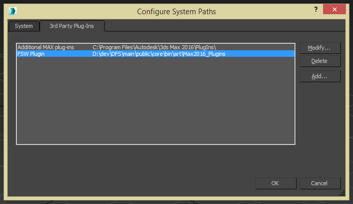 Select the 3rd Party Plug-Ins tab and press the Add button. A new dialogue appears in which the plug-in's path should be referenced. After a path has been given, press OK for both dialogues and restart 3ds Max. Select the 3rd Party Plug-Ins tab and press the Add button. A new dialogue appears in which the plug-in's path should be referenced. After a path has been given, press OK for both dialogues and restart 3ds Max.Upon relaunch, a new menu-bar item will appear called FSW Tools. In addition to this, a new material called FlightSimWorld becomes available in the Material Editor.
FSW Tools After installing the plug-in, a new menu appears under the main menu-bar called FSW Tools. This menu has a number of tools we shall explore in this section, some of which will be familiar to users of previous titles built with this engine. File Properties and Export ToolsThe File Properties and Export Tools dialogue holds some useful functions typically used before export. Specifying a GUID is the only mandatory option. - GUID: a Globally Unique ID (GUID) number, which will be associated with the asset in FSW.
- Create: generate a new GUID.
- Friendly: an alphanumeric string to accompany the GUID. It is human recognisable, whereas GUID's are not. Typically, the asset's filename can be used here.
- Edit: enable the user to enter a new friendly name.
- Get GUID from .x file: As the name suggests, this feature will allow the user to use an existing GUID stored within a .x. This is useful when replacing an existing .x file with new content.
- Model has shadow map?: Enabling this will cause the asset to render using cascade shadow-maps. It is designed chiefly for aircraft at this point in time due to the rendering expense.
- Export and Earth Curvature Tool:
- Export Model: These options allow the user to quickly export scenery objects by automatically invoking XToMDL and BGLcomp once a .X file is generated. Aircraft (and other animated content) is not fully supported at this stage. Note: the 3ds Max scene file must be saved prior to clicking EXPORT.
- Earth Curvature Tool:
- Deform Selected will apply small offsets to a selected mesh's vertices, consistent with real-world curvature. Using this feature is essential on 4000 metre long runways.
- Tessellate Selected will add additional vertices to a mesh at 100m intervals. This ensures the mesh has healthy topology for portraying the Earth's curve.
FSW Animation ManagerThe Animation Manager forms an interface between 3ds Max's intrinsic animation tool-set and FSW. It is used to tie animation key ranges (i.e. from frame 0 to frame 100) to animation functions within the modeldef.xml file. These animation functions return a number between 0 and 1. This number is scaled by the animation's duration (specified in the Animation Manager) and then used to determine which animation frame to play.
For example, an animation function returning 0.5 for an animation set-up in 3ds Max between frame 0 and 100 will display frame 50. - Update Sel: make selected geometry the active Node in the Animation Manager
- Animation List: a list of animation functions read from the modeldef.xml file.
- Groups: groups for jumping between animation function categories. Groups are defined in the modeldef.xml file
- Auto Rotate: automatically rotates active geometry Node. Use of this is discouraged.
- Start/End: the start and end frames in 3ds Max for the current animation.
- Create/Delete: Commit the current animation parameters to active geometry Node.
- Objects Anims: Displays any committed animations for the active geometry Node.
Attach Point ToolThe Attach Point Tool enables users to tie special behaviour to a geometry Node, such as specifying the location (and existence) of a particle emitter. - Mode: These options indicate the desired behaviour to associate with a geometry Node.
- Effect: attach a .fx particle emitter to selected geometry.
- Effect to attach: .fx files stored in the FSW effects directory will appear here.
- Effect Params: custom arguments/parameters.
- Library Object: attach a MDL library object.
- Object .x file: name of desired library object.
- Choose new library object: commit any library object stated in the previous parameter to selected geometry.
- Visibility: attach a condition to selected geometry's visibility.
- Visibility Objects: the visibility condition to attach; read from the modeldef.xml file.
- Mouse Rect: attach a click-tester to selected geometry.
- Mouse Rect Objects: the click-test function to attach; read from the modeldef.xml file.
- Platform: attach a land-able surface to selected geometry.
- Surface Type: the surface type. This influences thing such as SFX upon touchdown.
- No Crash: prevent collision detection for selected geometry.
- Offset from geometry: moves an Attach Point along selected geometry's surface normal.
- Attach name: name of Attach Point to be created. In most cases, leaving the default name in this field is fine.
- Attach to selected geometry: Commits Attach Point to selected geometry. The Attach Point is stored in a geometry Node's User Defined Properties (RMB → Object Properties → User Defined).
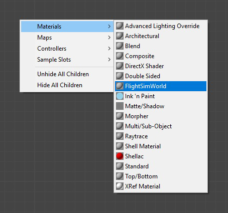
3ds Max MaterialAdding a New MaterialFSW materials are defined within the 3ds Max Material Editor. Right-click in the Material Editor's canvas and select Materials → FlightSimWorld. This will create a new FlightSimWorld material.
FlightSimWorld materials can be plugged into 3ds Max Multi/Sub-Object materials if desired.
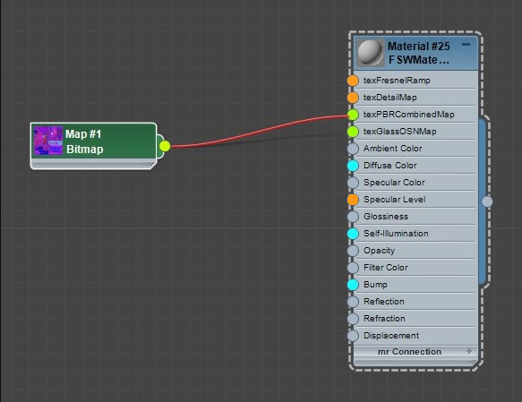
Material Texture SlotsTextures are assigned to FSW materials using Bitmap nodes.
First of all, create a Bitmap node, ensuring the file path points to the necessary bitmap file. Then plug the node into one of the following slots. Bitmap nodes can be created by dragging a DDS file into the 3ds Max Material Editor.
PBR Only |
Note: PBR materials require a valid texPBRCombinedMap, Diffuse Color and Bump map to be assigned. | Legacy Only |
- texFresnelRamp
- texDetailMap
- Specular Color
Note: texFresnelRamp and texDetailMap can only be applied by clicking the appropriate buttons in the "Other Texture Info" and "Fresnel Ramp" sections in the material's properties. | Common |
|
PBR MaterialThe PBR material is intended for use on all new content added to FSW. It is strongly advised the Physically-Based Rendering section is read thoroughly before creating PBR materials.
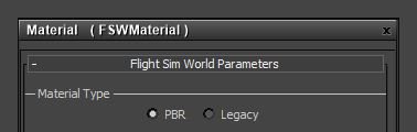 | Material Type: defines material as PBR or Legacy and alters material options accordingly. In this case, we want PBR. | 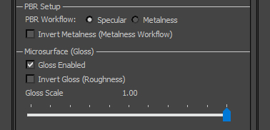 | PBR Setup: defines how Green channel of Combined Map is interpreted. - Specular: treats the Green channel as a Specular map and derives Metalness from Specular/Reflectivity value.
- Metalness: treats the Green channel as a Metalness map and derives Specularity/Reflectivity from Metalness value.
- Invert Metalness: interprets the Green channel's Metalness values inversely. This means 0 will indicate a metal and 255, a non-metal.
Microsurface (Gloss): defines how Red channel of Combined Map is interpreted. These options should be left alone except in special cases. - Gloss Enabled: enables reading of Glossiness from the Red channel.
- Invert Gloss: interprets Glossiness values inversely, treating them as Roughness values.
- Gloss Scale: coefficient (multiplier) for Glossiness values. This should be left at 1.00 with values being scaled in the texture instead.
| 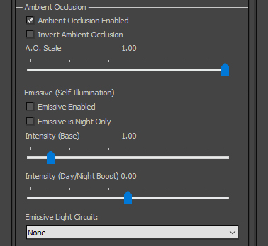 |
Ambient Occlusion: defines how the Blue channel of Combined Map is interpreted. These options should be left alone except in special cases.
- Ambient Occlusion Enabled: enables reading of Ambient Occlusion from the Blue channel.
- Invert Ambient Occlusion: interprets Ambient Occlusion values inversely, treating 0 as unoccluded and 255 as fully occluded.
- A.O. Scale: coefficient (multiplier) for Ambient Occlusion values. This should be left at 1.00 with values being scaled in the texture instead.
Emissive (Self-Illumination): defines how Emissive Map is interpreted.
- Emissive Enabled: enables reading of Emissivity.
- Emissive is Night Only: adds condition to only apply Emissivity at night.
- Intensity (Base): coefficient (multiplier) for Emissivity values. Values above 1.00 will cause HDR bloom.
- Intensity (Day/Night Boost): a boost applied to Base Intensity, either at Night (if negative) or Day (if positive). For example: a Base Intensity of 1.00 with a Boost Intensity of -1.50 will produce 1.00 Intensity during daytime and 2.50 Intensity at night-time.
- Emissive Light Circuit: adds condition to only apply Emissivity when selected lighting circuit is on. Menu options correspond to lighting circuits in the aircraft.cfg file.
| | 
|
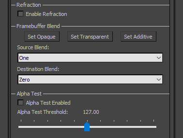
Refraction: used mostly for surfaces with Real-time Raindrop Effect applied. Other use cases include shattered aircraft glazing (e.g. bird strike effects).
Framebuffer Blend: used for materials with transparency to control their rendering.
- Set Opaque: applies Opaque preset to Source Blend and Destination Blend fields. This should be used for all Opaque objects and is applied by default.
- Set Transparent: applies Transparent preset to Source Blend and Destination Blend fields. Pixels using this setting will be interpolated against the frame-buffer pixels by the Albedo Map's Alpha channel. This should be used for materials with partial transparency (e.g. glass, acrylic, text overlay layers).
- Set Additive: applies Additive Transparent preset to Source Blend and Destination Blend fields. Pixels using this setting will be added to frame-buffer pixels. For example, a red pixel will add to the red channel of the frame-buffer whereas a black pixel (0,0,0) will have no effect. This setting should only be used in very special cases (e.g. fighter jet HUD graphics, light bloom sprites). Also note that this setting will prevent the material from receiving any lighting contribution from light sources in the environment.
Alpha Test: provides an additional, often more efficient method for achieving full transparency within a material. Pixels within a material with Alpha Test enabled are not drawn to the frame-buffer, and hence appear fully-transparent, wherever the Alpha channel of their Albedo Map is below the Alpha Test Threshold value. This allows for full transparency in areas of an Opaque material, which is a more efficient alternative to using a Transparent material. Drawbacks of Alpha Test can include more noticeable aliasing around edges of transparent areas. | | 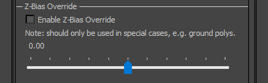
|
Z-Bias Override: affects the order in which the entire object is drawn, as well as the manner in which the material is drawn to the Depth Buffer. This feature should only be used for ground polys, where it is intended to prevent the ground poly from drawing beneath the terrain or other ground polys with a larger Z-Bias Override value. | | 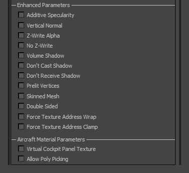
|
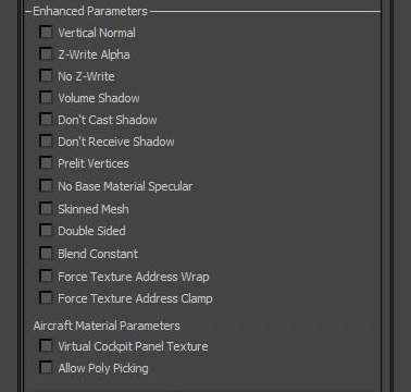
Enhanced Parameters: special boolean parameters.
- Additive Specularity: intended only for Set Transparent PBR materials, this property causes the specular portion of reflected light to be added directly the frame-buffer (similar to the Set Additive preset) whilst the diffuse portion continues to be multiplied by the alpha channel. This can allow for bright sun reflections on highly transparent surfaces, such as glass. Note that where the Albedo Map's alpha channel is exactly 0, no specular reflections will be present.
- Vertical Normal: forces vertex normals to point upward in world-space. This is useful for blending grass shading with terrain shading.
- Z-Write Alpha: forces Transparent materials to write to the Depth Buffer.
- No Z-Write: forces Opaque materials not to write to the Depth Buffer.
- Volume Shadow: enables volume shadows, which are sometimes used for scenery assets.
- Don't Cast Shadow: suppresses geometry from casting shadows. It should always be used on aircraft glazing.
- Don't Receive Shadow: suppresses geometry from receiving shadows. This is only relevant for models using Cascade Shadow Mapping.
- Prelit Vertices: suppresses lighting calculations, substituting regular shader output with Albedo Map's texel colours. In most cases, an Emissive Map should be used instead of this.
- Skinned Mesh: enables skinning. Use cases include characters and aircraft wing flex.
- Double Sided: suppresses back-face culling and applies inverse normals to a polygon's back-faces.
- Force Texture Address Wrap: forces textures to repeat beyond 0-1 UV range. Example: U = 1.5 ≡ 0.5
- Force Texture Address Clamp: force textures to clamp beyond 0-1 UV range. Example: U = 1.5 ≡ 1.0
Aircraft Material Parameters: special boolean parameters specific to aircraft.
- Virtual Cockpit Panel Texture: inverts UV map's V axis. This is sometimes useful for dynamic textures although unnecessary.
- Allow Poly Picking: activates click-testing. See Poly-picking for more information.
|
Legacy MaterialThe Legacy material exists to support old assets and should be avoided for any new content. 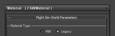 |
Material Type: Defines material as PBR or Legacy and alters material options accordingly. In this case, we want Legacy. | 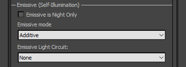 |
Emissive (Self-Illumination): defines how traditional Emissive Map is interpreted.
- Emissive Mode: defines how Emissive values are blended into Framebuffer.
- Additive: adds Emissive values to Framebuffer.
- Blend: linear interpolates Emissive values against Framebuffer.
- MultiplyBlend: multiplies Emissive values by Diffuse values.
- Emissive Light Circuit: adds condition to only apply Emissivity when selected lighting circuit is on. Menu options correspond to lighting circuits in the aircraft.cfg file.
| 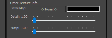 |
Other Texture Info: allows a small, frequently repeating texture to be applied alongside the standard textures. This is often known as a Detail Texture.
- Detail Map: slot into which Detail Texture is entered.
- Detail: a divisor for the UV's, thus controlling the frequency by which Detail Texture repeats. Greater numbers lead to greater repetition and a finer overall texture.
- Bump: a divisor for the UV's, thus controlling the frequency by which Bump Detail Texture repeats. Greater numbers lead to greater repetition and a finer overall texture. The Bump Detail Texture is generated from the Detail Texture.
| | 
|
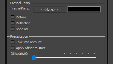
Fresnel Ramp: this is used to calculate traditional Fresnel effects on traditional Diffuse, Reflection and Specular textures. The Fresnel Ramp's U coordinate is determined based upon the angle between camera and vertex normal.
- FresnelRamp: slot into which Fresnel Ramp is entered.
- Diffuse: Fresnel affects the diffuse texture. Based on angle of view, the colour of the Fresnel ramp will affect the diffuse texture. Black in the Fresnel ramp makes the diffuse texture black. Red will tint it red.
- Reflection: Fresnel affects reflection texture.
- Specular: Fresnel affects specular texture.
Precipitation: causes Specularity lighting pass to be conditional on weather. When raining, Specularity is calculated; otherwise it is skipped. This gives legacy runways their wet sheen in rainy conditions.
- Take into account: enables the effect.
- Apply offset to start: causes the effect to be transitioned in gradually rather than just appearing.
- Offset: species extent of the transition.
|
|
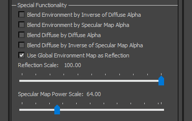
Special Functionality: legacy reflection cube-map options (deprecated). | | 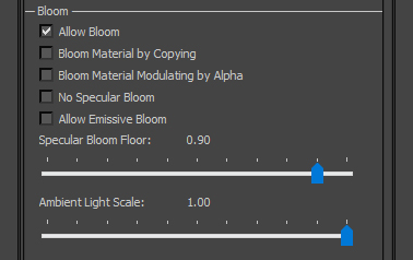
|
Bloom: legacy bloom (deprecated). | 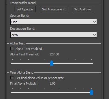 |
Framebuffer Blend: used for materials with transparency to control their rendering.
- Set Opaque: applies Opaque preset to Source Blend and Destination Blend fields. This should be used for all Opaque objects and is applied by default.
- Set Transparent: applies Transparent preset to Source Blend and Destination Blend fields. Pixels using this setting will be interpolated against the frame-buffer pixels by the traditional Diffuse Map's Alpha channel. This should be used for materials with moderate to high Diffuse values, which create an obstructive transparency effect (e.g. see-through plastic, latex gloves).
- Set Additive: applies Additive Transparent preset to Source Blend and Destination Blend fields. Pixels using this setting will be added to frame-buffer pixels. For example, a red pixel will add to the red channel of the frame-buffer whereas a black pixel (0,0,0) will have no effect. This should be used in very special cases (e.g. fighter jet HUD graphics, light bloom sprites). Also note that this setting will prevent the material from receiving any lighting contribution from light sources in the environment.
Alpha Test: provides an additional, often more efficient method for achieving full transparency within a material. Pixels within a material with Alpha Test enabled are not drawn to the frame-buffer, and hence appear fully-transparent, wherever the Alpha channel of the Diffuse Map is below the Alpha Test Threshold value. This allows for full transparency in areas of an Opaque material, which is a more efficient alternative to using a Transparent material. Drawbacks of Alpha Test can include more noticeable aliasing around edges of transparent areas.
Final Alpha Blend: replaces the traditional Diffuse Map's Alpha value by one specified in the material. This can be used if a material's Transparency is uniform (i.e. does not vary).
- Set final alpha value at render time: activates the Alpha override.
- Final Alpha Multiply: value to replace material's standard Transparency value.
| | 
|
Z-Bias Override: affects the order in which the entire object is drawn, as well as the manner in which the material is drawn to the Depth Buffer. This feature should only be used for ground polys, where it is intended to prevent the ground poly from drawing beneath the terrain or other ground polys with a larger Z-Bias Override value. |
| Enhanced Parameters: special boolean parameters. - Vertical Normal: forces vertex normals to point upward in world-space. This is useful for blending grass shading with terrain shading.
- Z-Write Alpha: forces Transparent materials to write to the Depth Buffer.
- No Z-Write: forces Opaque materials not to write to the Depth Buffer.
- Volume Shadow: enables volume shadows, which are sometimes used for scenery assets.
- Don't Cast Shadow: suppresses geometry from casting shadows. This is only relevant for models using Cascade Shadow Mapping. It should always be used on aircraft glazing.
- Don't Receive Shadow: suppresses geometry from receiving shadows. This is only relevant for models using Cascade Shadow Mapping.
- Prelit Vertices: suppresses lighting calculations, substituting regular shader output with traditional Diffuse Map's texel colours. In most cases, a traditional Emissive Map should be used instead of this.
- Skinned Mesh: enables skinning. Use cases include characters and aircraft wing flex.
- Double Sided: suppresses back-face culling and applies inverse normals to a polygon's back-faces.
- Force Texture Address Wrap: forces textures to repeat beyond 0-1 UV range. Example: U = 1.5 ≡ 0.5
- Force Texture Address Clamp: force textures to clamp beyond 0-1 UV range. Example: U = 1.5 ≡ 1.0
Aircraft Material Parameters: special boolean parameters specific to aircraft.- Virtual Cockpit Panel Texture: inverts UV map's V axis. This is sometimes useful for dynamic textures although unnecessary.
- Allow Poly Picking: activates click-testing. See Poly-picking for more information.
|
|