Change List A list of changes made to this document.
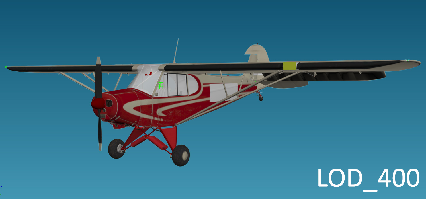
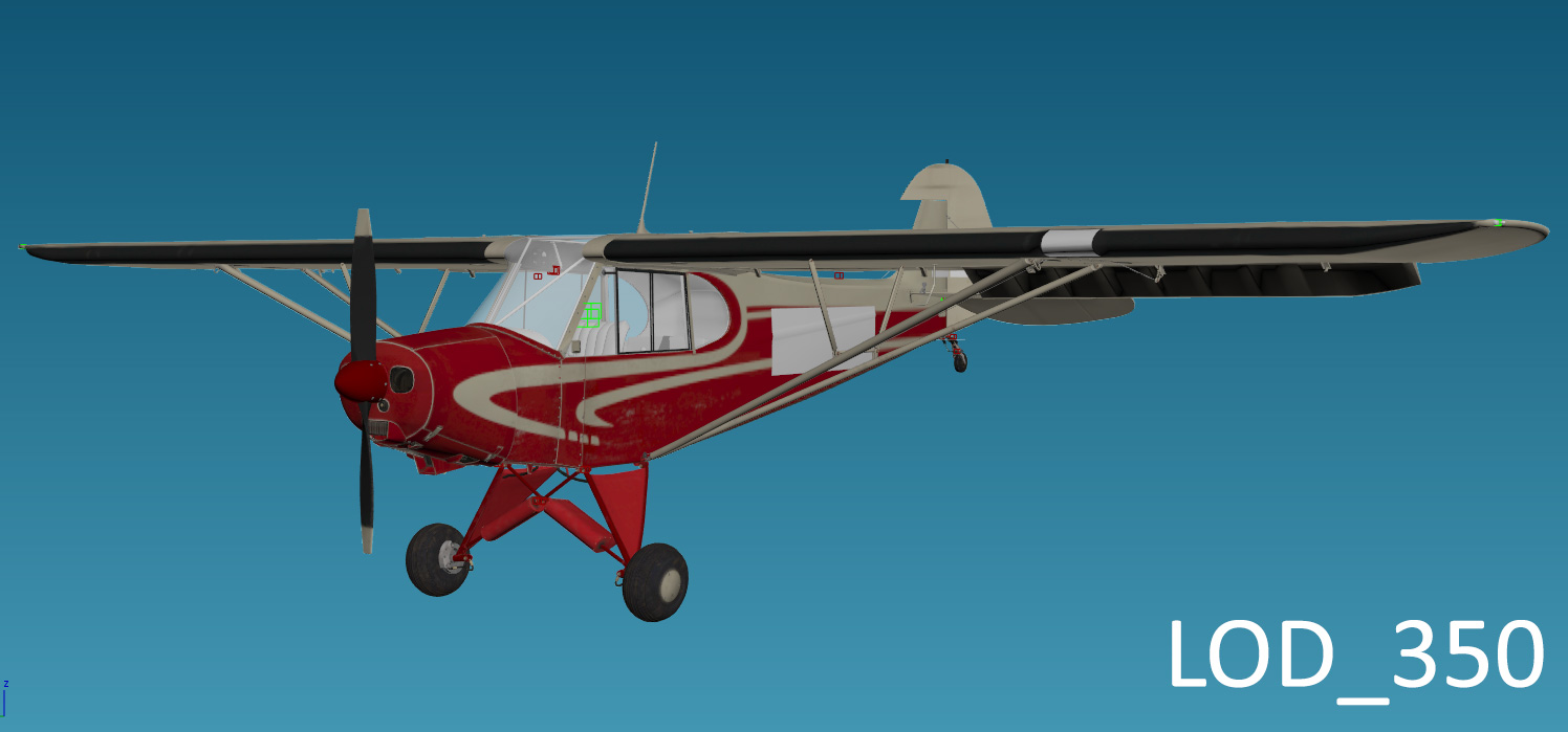
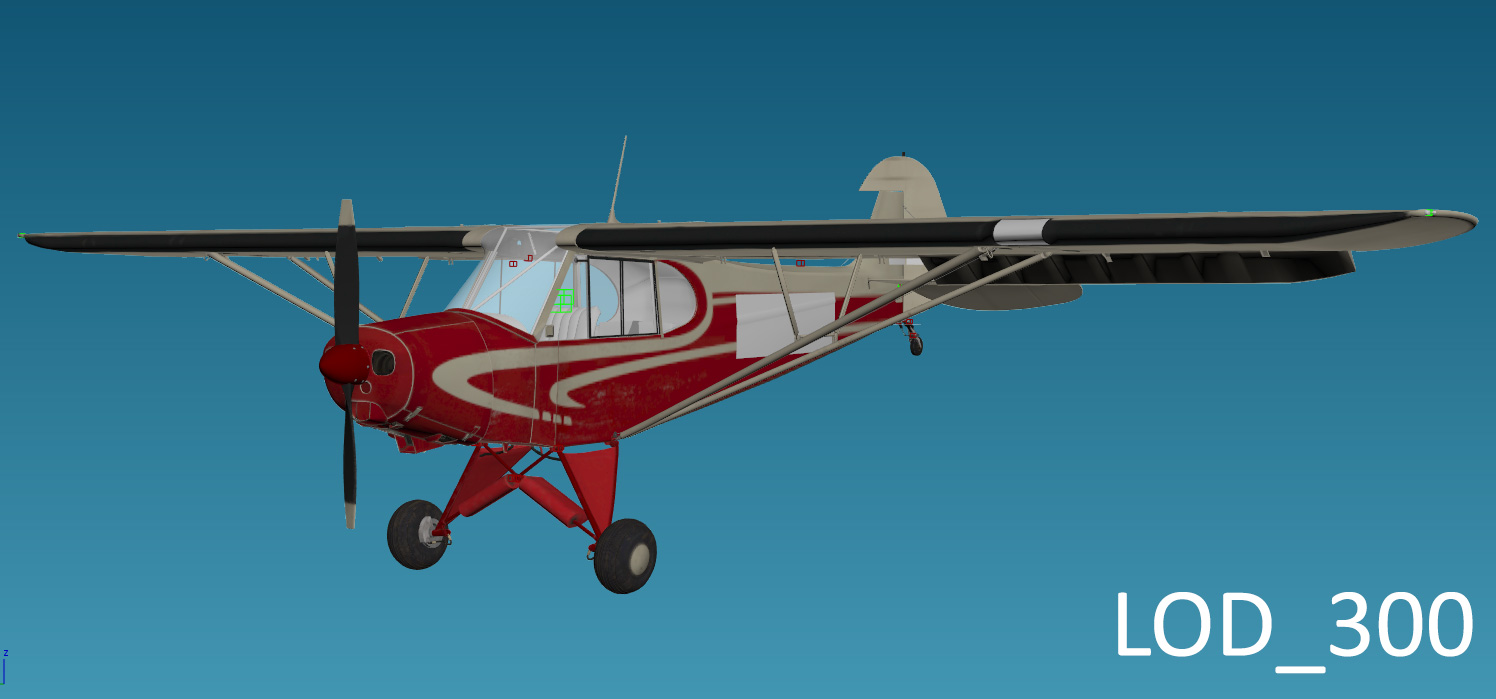
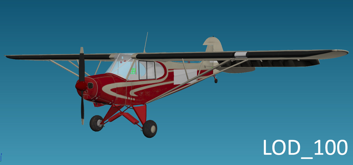
Level of Detail Meshes (LODs)For the time being, the LOD system in FSW is identical to that used in previous titles built with this engine. Interior models do not use LODs though should still be exported with both a LOD_400 and root node. Attachpoints must not be duplicated into multiple LOD layers. Every attachpoint must be unique. The section, Aircraft Export Procedures, advises on handling aircraft LOD exports. Please refer to it for additional information. LODs are important for performance, especially in the realm of FSW's capability in handling high-detail models. It is wasteful to render all parts of a model at distances things will not get seen, for example in the screenshot to the right. 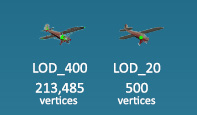 WorkflowThe primary LOD level is LOD_400. Every LOD further down the tree takes the previous level as a base, removing unnecessary geometry, items and edge loops to suit. LOD_10 and LOD_5 are specifically designed low poly models designed to capture the form and silhouette of the aircraft without any attention to animated parts or specific details. A Dummy node (Create → Helpers → Dummy) is used to store the contents of a given LOD. The Dummy node is suffixed with _LOD_ followed by a number indicating when the LOD is shown. Let's use _LOD_300 in 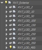 the image to our right as an example. When the asset (i.e. RV7 aircraft) occupies more than 300 screen pixels, but less than 350, _LOD_300 is the active LOD node. The moment the asset occupies 350 screen pixels or greater, _LOD_350 becomes the active LOD node. This continues up the chain until we reach the highest LOD node. the image to our right as an example. When the asset (i.e. RV7 aircraft) occupies more than 300 screen pixels, but less than 350, _LOD_300 is the active LOD node. The moment the asset occupies 350 screen pixels or greater, _LOD_350 becomes the active LOD node. This continues up the chain until we reach the highest LOD node.Example LOD StructureThe below table and screenshots demonstrate LODs for the PA18 in Flight Sim World. Vertice count decreases aggressively with each LOD level despite there not being an appreciable difference visually. The pixel number of each LOD node is not set in stone and should be customised for each application. For example, PA18 uses LOD_10 and LOD_5 whereas the RV7A uses LOD_10 and LOD_2.
LOD Level DescriptionsThe following table describes how each LOD level changes when compared to the previous.
Using set theory as an example: LOD 1
LOD 2
LOD 3
LOD 4
|
Art Authoring >