Change ListA list of changes made to this document.
|
 Theory
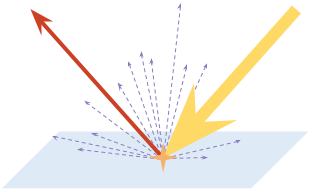
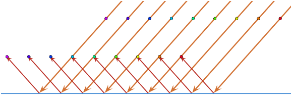 | 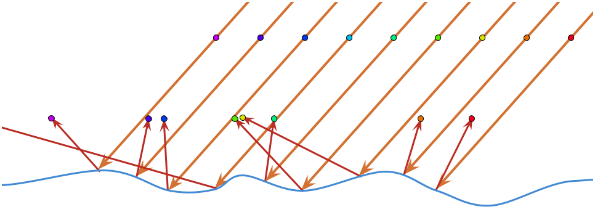 |
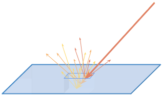
Imagine two parallel light rays a few nanometres apart. A smooth surface such as a mirror will reflect these rays such that they remain near parallel; whereas a rough surface may send them off in completely different directions. A pattern (such as a face) formed by the incoming light will be retained by the former case, and scrambled by the latter.
A mirror is an example of a smooth surface with uniform angles of reflection, whereas concrete is an example of a rough surface with inconsistent angles of reflection. Both materials reflect a lot of light as specular energy, but you cannot see your own face in concrete.
Conservation of Energy
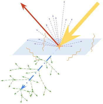
The Law of Conservation of Energy states that the total energy of an isolated system remains constant over time.
Within the context of light, this means all energy from a ray of light striking a surface will be accounted for in the interaction. Of the total energy, some will be reflected by the surface, some will be transmitted through the surface, and the remaining quotient will be absorbed (and perhaps emitted in another form such as heat).
PBR systems uphold the Law of Conservation of Energy by accounting for all light emitted by light sources. The game world can be thought of as an isolated system. This means that a PBR material cannot, for example, reflect more light than it receives.
Fresnel Reflection
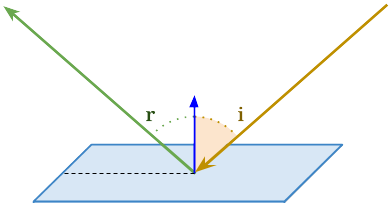
The extent of a material’s specular reflectivity varies according to the angle of incidence. At greater angles (known as grazing angles), specular reflectivity approaches 100%. We refer to this phenomenon as Fresnel reflection.
We can think of a material as possessing a base reflectivity. This is the amount of specular reflectivity exhibited for a light ray with an angle of incidence of 0°. As the angle of
incidence increases, so does the amount of specular reflectivity until it eventually reaches 100%.
The relationship between angle of incidence and specular reflection is a function that can be mapped-out onto a graph.
The shape of the curve varies from material to material, but it always starts at the material’s base reflectivity value and ends up at 100%. Dielectrics (i.e. non-metals) have distinct Fresnel curves to metals.
Fresnel reflection is an incredibly important aspect of a material’s aesthetic, but due to its subtle nature, it is rarely thought about outside of a physics laboratory.
Thankfully for the artist, Fresnel reflection is applied by a PBR shader without the artist needing to pay too much consideration to its presence. A specular reflectivity map can be thought of as describing the material’s base reflectivity.
Application
 In the theory section, we explored possible outcomes of light interacting with a material. As discussed, each of these outcomes has a probability specific to the material in question. A PBR texture set defines these probabilities.
A PBR texture may, for example, indicate that 50% of received light is reflected via diffuse reflection. It would do so by having a colour value of 50% (<127, 127, 127> in RGB). However, this begs an important question: what if specular reflectivity is specified at greater than 50%? The shader resolves this by decreasing the diffuse reflectivity such that total reflectivity is no greater than 100%. Artists must be mindful of this fact and use physically-correct colour values.
Typically, a PBR texture set will contain the following maps:
Albedo
Describes the proportion of diffuse reflection produced by a material.

<127, 0, 0>
50% diffuse reflection probability for red light wavelengths; 0% otherwise. In total 16.6% of light is reflected via diffuse reflection.
Normal
Describes pixel normals in tangent-space. Normal maps are applied no differently within a PBR system.

<127, 127, 255>
Pixel normals perfectly aligned to corresponding vertex normals.
Microsurface
Describes the average angle between microfacets. A more intuitive way to think of this is as the material’s roughness value.

<138>
54% deviation from a perfect surface, producing blurry yet discernible specular reflections. This is the value of glossy plastic.
Emission
Describes total light emitted by a material (incandescence). 100% represents an arbitrary maximum value.

<255, 220, 180>
86% light emittance with a bias toward ‘warm’ wavelengths, producing a soft orange colour.
Specularity
Describes the proportion of specular reflection (base reflectivity) produced by a material.

<76>
30% specular reflection probability.
Metalness
Describes whether or not a material is metallic. While intermediate values (between 0% and 100%) can be used, they will not produce physically-accurate results in most situations.

<0>
0% metalness. A dielectric (non-metal).
Opacity
Describes the proportion of unscattered light transmitted through the material.

<40>
16% opacity; most light is transmitted through the material. This is approximately the value of glass.
Ambient Occlusion
Describes how much ambient light is occluded from a region due to the concavity of its macroscopic form.

<241>
5% occluded. This is typical for a mostly convex region.
Maps
FSW utilises all of these texture types, but expects them to be packed into four distinct image files:
Albedo Map
Combined Map
Calibrating PBR (Gamma-Space)
In FSW, it is important that all textures be in the correct colour/gamma space. Until now we have assumed a linear colour-space for our examples.
Gamma correction is a means to optimise the storage of data when encoding an image by exploiting the non-linear manner in which humans perceive light and colour. Humans perceive brightness on a curve. Greater sensitivity is accorded to the brightness steps between darker tones than between lighter ones. An image without gamma correction allocates too much data to highlights and too little data to shadow (where humans have the finest sensitivity). sRGB is a common implementation of gamma correction; sometimes “sRGB” and “gamma correction” may be used interchangeably.
As a PBR texture set describes physical material properties rather than serving to look pretty in Photoshop®, using gamma correction is not particularly useful. In fact, it poses two problems:
- Linear spectra (such as fractions of reflected light) have lower resolution as values increase.
- It is confusing for the artist as middle-grey (<127, 127, 127> in RGB) does not represent 0.5.
Linear | 0.0 | 0.1 | 0.2 | 0.3 | 0.4 | 0.5 | 0.6 | 0.7 | 0.8 | 0.9 | 1.0 |
Gamma | 0.0 | 0.1 | 0.2 | 0.3 | 0.4 | 0.5 | 0.6 | 0.7 | 0.8 | 0.9 | 1.0 |
Depending on type and the art workflow used, FSW requires that some textures be linear, and others gamma-corrected (in sRGB):
- Albedo – sRGB
- Combined texture
- Gloss/Roughness (Red) channel – linear
- Specular (Green) channel
- Metalness (Metalness flow) – linear
- Reflectivity (Specular flow) – linear
- Ambient Occlusion (Blue) channel – linear
- Emissive – sRGB
The artist must be mindful of this when looking up PBR values for materials online. There are various resources from which albedo, roughness, and specular values can be garnered, such as:
- Unity: Material Charts
- Physically-Based Materials
- Working with Physically-Based Shading: A Practical Approach
- DONTNOD Physically-Based Rendering Chart for Unreal® Engine® 4
- Tutorial: Physically-Based Rendering, and You Can Too!
- The Comprehensive PBR Guide
These resources will generally state whether the values are linear or gamma corrected. When a given material cannot be found online, its values can be intelligently guessed using a material with similar properties for reference.
In Photoshop®/GIMP, this process can be performed over the whole image (to one or all colour channels), to convert values from sRGB into linear (gamma = 0.45) or linear into sRGB (gamma = 2.2).
- Photoshop®: Image > Adjustments > Levels > enter gamma value (middle box, with “1.00”) > OK
- GIMP: Colours > Levels… > enter gamma value (middle box, with “1.00”) > OK
In both Photoshop® and GIMP this process can be performed on a single channel only by selecting the channel in the “Channel:” drop-down box in the Levels window.
An image/colour channel converted from sRGB into linear space will typically appear darker, and vice-versa. These methods are also valid for converting other types of values/textures between sRGB and linear space where required.
Converting a value from sRGB to linear:
(Where 0.04 is the linear reflectivity value, and would represent a non-metal)
- sRGB (integer) = 51 (out of 255)
- sRGB (decimal) = 51/255 = 0.20
- Linear (decimal) = 0.20^2.2 = 0.04
Converting back, from linear to sRGB:
- Linear (decimal) = 0.04
- sRGB (decimal) = 0.04^0.45 = 0.20
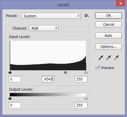 | 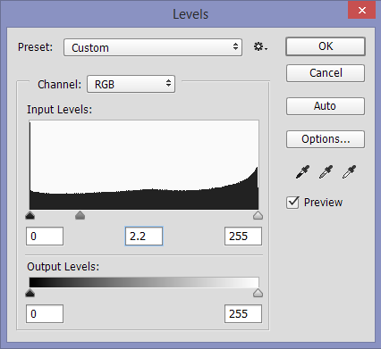 |
| Figure 13: 0.4545 converts from sRGB to linear | Figure 14: 2.2 converts from linear to sRGB |
PBR Material Reference Table
The following tables demonstrate true PBR values of common materials.
They can be used as a starting-point when portraying a given material. Note that non-metals tend to have reflectivity values below 0.1 (linear), whereas metals tend to have reflectivity values above 0.5 (linear). Further, non-metal reflections are almost never change the colour of light, whereas metallic reflections do.
When it’s not possible to find the real-world reflectivityvalue for a non-metal, 0.04 (linear) or 0.23 (sRGB) is often a suitableapproximation to use.
Dielectrics (Non-Metals)
Material | Reflectivity (Linear) | Reflectivity (sRGB) |
Ice | 0.018 | 0.16 |
Water | 0.020 | 0.17 |
Skin | 0.029 | 0.20 |
Hair | 0.047 | 0.25 |
Plastic | 0.032 - 0.043 | 0.21 - 0.24 |
Glass | 0.032 - 0.076 | 0.21 - 0.31 |
Ruby | 0.076 | 0.31 |
Diamond | 0.172 | 0.45 |
Chalk | 0.043 | 0.24 |
Quartz | 0.045 | 0.25 |
Crystal | 0.111 | 0.37 |
Metals
Material | Reflectivity (Linear) | Reflectivity (sRGB) |
Iron | 0.563, 0.579, 0.579 | 0.77, 0.78, 0.78 |
Copper | 0.956, 0.646, 0.547 | 0.98, 0.82, 0.76 |
Gold | 1.000, 0718, 0.290 | 1.00, 0.86, 0.57 |
Aluminium | 0.914, 0.914, 0.935 | 0.96, 0.96, 0.97 |
Silver | 0.957, 0.935, 0.893 | 0.98, 0.97, 0.95 |
Chromium | 0.554, 0.554, 0.554 | 0.76, 0.76, 0.76 |
Titanium | 0.542, 0.500, 0.448 | 0.76, 0.73, 0.69 |
Nickel | 0.660, 0.609, 0.526 | 0.83, 0.80, 0.75 |
Troubleshooting
1. Materials appear dark or have dark/grey/metallic patches on them
This can be caused when reflectivity values for a non-metal arefar above suitable values, and the shader treats some or all of it as a metal. Thiswould likely be caused by the reflectivity values not being physically correctto begin with, or the values being stored in sRGB space instead of linear spacein the final texture (if using the specular workflow).
2. Specular reflections on glass/transparent materials are too dim when usingthe additive specular material flag
This could be because the alpha value for the material is set to 0. The flag does not affect areas of the material where the alpha value is exactly 0.
3. Some details are missing from metallic surfaces
Check that the details have correct reflectivity values in the combined map (i.e. a non-metal value where there is paint, etc).
4. Metals look different compared to other PBR engines (specular workflow)
Check that the albedo value for the metal is black in both engines (as metals should have no diffuse reflections).
Texture-Geometry Dichotomy
Let us start by exploring what shouldn’t be included in a texture.
Traditionally, it was standard practice for the artist to imply the existence of small geometric forms in a texture set. This was due to limitations of the time, and generally yielded unrealistic results. Development teams were forced to make visual compromises for performance.
As time progressed, this practice became less and less commonplace. During the N64/PS1 era, only the most obvious aspects of form were conveyed through 3D geometry; everything else (including a character's facial features) were packed into textures. Two generations later, developers began conveying facial features such as eyeballs through 3D geometry. Now we are at a stage where nearly all form can be conveyed through 3D geometry.
Within a PBR context, the practice of packing geometric form into textures makes even less sense. Each texture has a specific purpose in describing the physical properties of a material, and should not be stuffed full of fake visual information.
As a general rule of thumb, it is okay to put geometric form smaller than 2cm into textures provided the textures within a texture set are consistent with one another. This is only a loose rule, however, as other factors must be considered — such as how close the camera is likely to come to the geometric form in question.
See Colour Maps for clarification on how best to convey small geometric forms in textures.
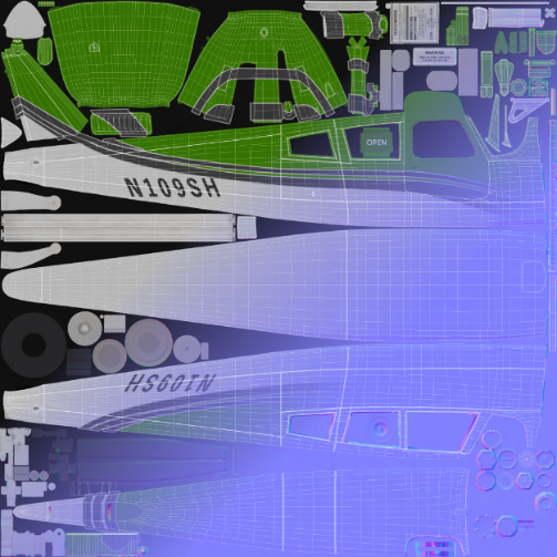
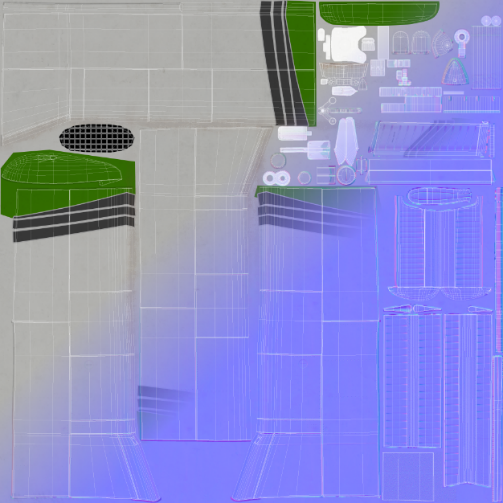
UV Layout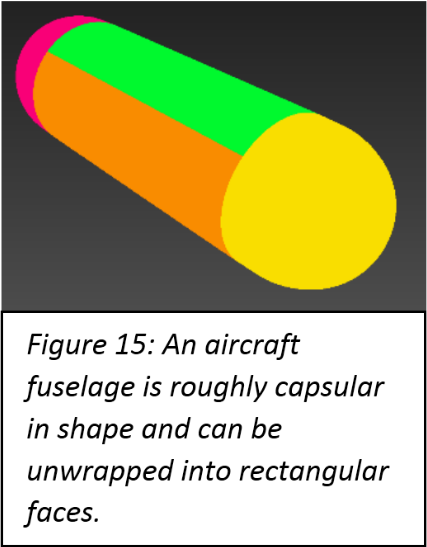
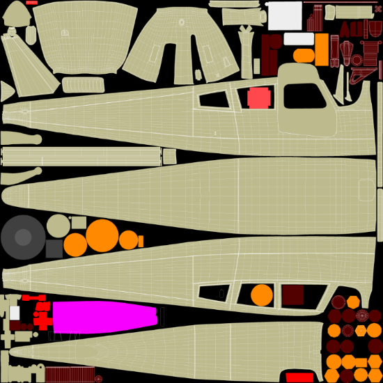
For light aircraft, the fuselage, wings and interior geometry should all be given their own UV maps.
The fuselage is approximately spherocylindrical in shape and should be unwrapped into a rectangle’s net with the bottommost piece vertically centred in the UV map. The front and rear sections of the fuselage vary too much from aircraft-to-aircraft for a rule to apply.
The wings should be unwrapped in a similar manner such that a wing has one UV Island for its up-facing elements and one UV Island for its down-facing elements.
Discretion should be applied as no two aircraft are identical and what generally applies may not be applicable in specific cases.
 |  |
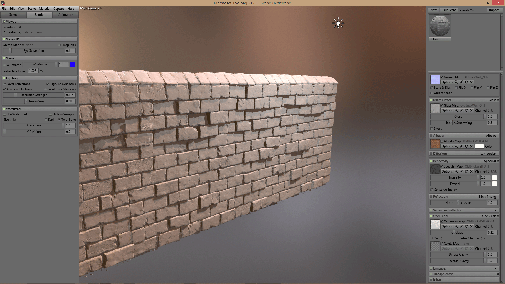
Texture Baking: AO & Normals
FSW aircraft typically have both ambient occlusion and normal information baked into their texture maps. There are a number of ways to go about this.
Both types of information can be captured in 3DS Max using a Projection modifier in conjunction with the Render to Texture dialogue. Many artists, however, prefer a freeware program called xNormal (available for download here: xNormal Installer).
xNormal is an excellent program and delivers industry-standard results. It is necessary for the aircraft to be exported from 3DS Max in FBX (or OBJ) format, and then imported into xNormal.
It may be useful to bake-out world-space and tangent-space normal maps, as many modern PBR texturing tools take world-space normal maps as input
Texture Baking: Colour Maps
Colour maps (known also as Material Maps) are a way to easily differentiate between different material types. They can aid the artist while texturing in Photoshop® and are used as input by many modern PBR texturing tools.
Unlike ambient occlusion and normal information, it is far better to use 3DS Max for baking colour maps into textures.
A colour map can be created in 3DS Max by assigning a different 3DS Max ‘Standard’ material to different pieces of geometry. By assigning each material its own diffuse colour, and then using the Render to Texture dialogue to instigate a bake, a colour map will be produced. It is advisable to use a skylight as the only light source and disable any advanced lighting options to prevent shading from appearing in the colour map.