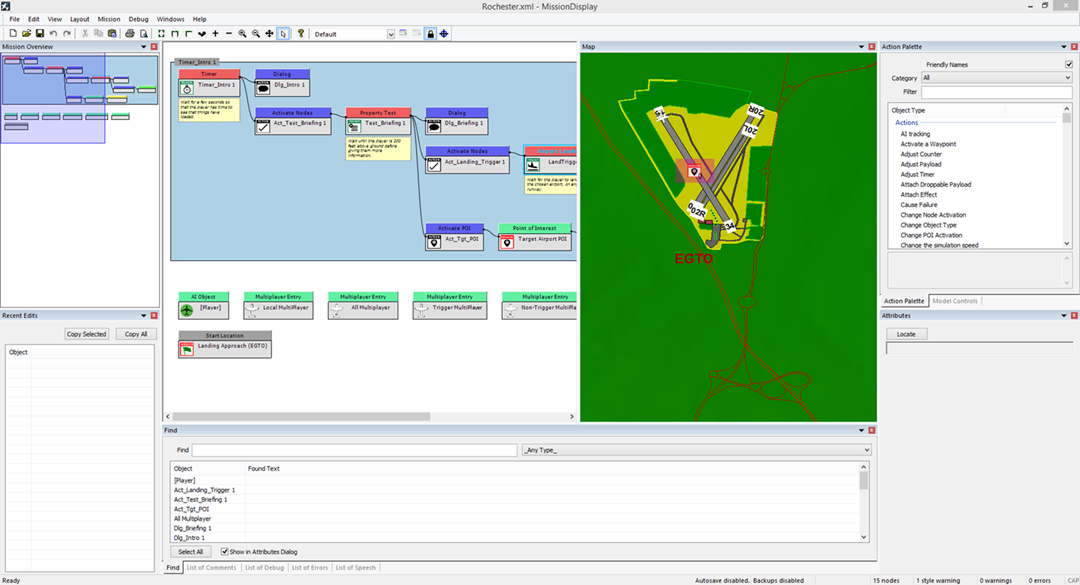
So you’ve now created a mission using the wizard. You’ll see on screen that a
number of elements now have data in them as shown in Figure 1.19.
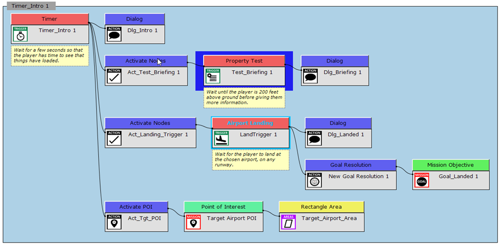
Figure 1.19. The Landing Approach mission.
You can see the boxes within the Mission Overview window and the Event
Viewer. The core group is called “Timer_Intro 1” which is the name of the first
node within the code. At the bottom of the Event Viewer are two nodes, these
are independent of the code and do not need to be attached to any other
nodes.
-
Mission Data
: This contains core information about the mission. If you double
click on the node, you’ll see the mission’s properties which contain
data about
its difficulty, specific messages and what category the mission belongs
to.
-
FlightFile
: This is where the player will start their journey within the mission,
if you double click on this node, the map will take you to this specific
object
which is represented by an aircraft. This aircraft will be sat on Runway
16 as
setup in the Mission Wizard.

|
Note: To zoom in and out of the map you can use the mouse scroll
wheel or the +/- keys. Ensure that the mp window is selected before
trying to zoom.
|
Updating the Mission Properties
Double click on the Mission Data node to launch the attributes for the mission
and change the following items:
- Change Estimated Time to: “7 minutes”.
- Change Success Message to: “You landed successfully”.
- Change the Category Ref to: “Approaches”.
|
|
Note: The Category Ref defines which group this mission belongs to. Initially
it is set to a random GUID which will create an error if not changed.
|
|
|
Note: GUID stands for "Globally Unique Identifier". The Pro Mission Tool
uses GUIDs through-out and is often used to identify unique instances such
as cameras, characters and items.
|
Updating the Aircraft's Starting Location – Flight File
At the moment we have an aircraft that will start on the runway, whereas we
want the aircraft to start in the air.
- By double clicking on the FlightFile node you can gain access to the aircraft
data. If
you now left click and hold the mouse button over the aircraft you will be
able to
drag it within the map. Drag the aircraft upwards (North) so that it’s a short
distance
away from the airport just before the river (If the aircraft does not move,
see note
below).
- Within the FlightFile Attributes Dialogue change the “Position | Altitude” option
to
read 1500ft.
- Change the Orientation | Heading to 180 so that it is facing South.
- Untick “Sim on Ground” as this will plant the plane onto the ground, regardless
of
the altitude that has been set.
- Change Fuel | Left Main to: 40.0
- Change Fuel | Right Main to: 40.0
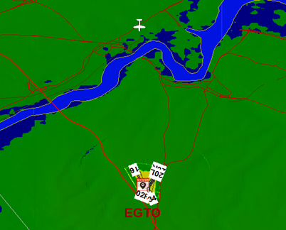
The map should now look something similar to Figure 1.20.
Figure 1.20. The current map.
|
|
Note: If you are unable to move the plane, ensure that Model Controls | Edit
Models is selected, this allows the objects to be moved around the world.
|
Updating the Point of Interest
A Point of Interest marker (POI) shows the player where to fly to within the
game world. In complex missions there may be multiple POI markers leaving a
breadcrumb trail for the player.
When creating the mission using the Wizard the game will have already created
a POI, but it won’t be in the exact position that we want it to be in. We want
it
to be at the end of the runway, showing the player which runway they should
land at.
- Within the Event Viewer find the “Point of Interest | Target Airport POI” node
and
then double click on it to bring up the Attributes for this node.
- At the Relative To option change it from Object to “Position”. This will now
place the
object on screen so that it can be moved around.
- Double click on the “Point of Interest | Target Airport POI” node, this will
then take
you to the object which will now need to be dragged to the correct runway which
in this case is 20R (if you have zoomed into the map you’ll probably already
be able
to see it). You will need to zoom in multiple times and move the icon more
precisely.
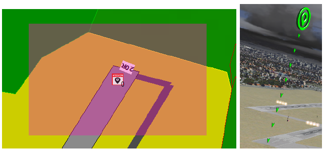
You should place it at the end of 06R as shown in Figure 1.21.
Figure 1.21. The Point of Interest marker on the map. The cross in the middle of
the icon denotes the center of the object. Figure 1.22. The object in the game
world.
Changing the Structure of the Code
As we used a Wizard to create this mission the structure of the mission isn’t
quite what we want it to be. The Wizard expected the plane to start on the
ground (which we have now moved) and goes through a number of steps to get
the player into the air.
The Wizard mission code follows the following process:
- Timer starts and activates the next bit of code at 3 seconds.
- Dialog plays, welcoming the player to the mission and asking them to climb
to
200ft.
- There is a property test which activates at any altitude above 200 ft, which
then
plays further VO, telling the player that they can fly around a bit before
landing.
- This will then activate two further nodes, the first is to check for the
player
landing (and won’t activate until the player comes to a full stop at KLAX).
- Activate a POI marker which will display the marker at the start of the runway
to show the player where to land (we amended the position of this item
in the
previous section).
Shortly we will change the code by:
- Amending the first VO to talk about landing rather than take off.
- Remove code that is currently being activated by the greater than 200 ft.
- Remove a Dialog node that talks about flying around before landing.
- Add a new activation node and move all other important code under it.
- Remove duplicate code.
|
|
Note: In reality we could leave the property test node in place as the aircraft
is already above 200 ft, but it's important when writing Pro Mission Tool
logic to keep it as clear and concise as possible.
|
|
|
Note: Code such as the 200 ft logic could play at unexpected times, so in
this case you wont be at 200 ft to begin with but later on in the mission
if you go below and above 200 ft as you prepare to land the code could
trigger. It's important to consider how your code could be activated by
other users.
|
Changing Dialog Text and VO
As this mission has been generated by a Wizard it starts off by telling the player
that they can take off and climb to 200 feet. For this mission we have amended
the starting location so that the aircraft is on its way to landing at an airport
and so the message text is no longer correct.
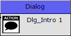
You can see text and VO messages within the Event Viewer with an icon of a
character talking as shown in Figure 1.23.
Figure 1.23. Dialog option.
- Double click the Dialog node called “Dlg_Intro 1”.
- In the Attributes for the Dialog node, replace the Text with the following:
“Rochester Tower, Piper Eight Foxtrot Juliet on Final Approach to Runway 20
Right.”
- If you click on the Play button next to the Sound File Name you will hear that
the VO is different to the text.
- You’ll need to record your own VO that reflects this new text. You’ll need to
replace
the original generated file called “NT14_001.wav”, with your recorded VO.
All audio for your mission is stored in the Sound folder within the mission
folder.
Steam\steamapps\common\DFS\missions\My Missions\WizardMission1\
Sound
|
|
Note: If you create multiple missions using the Wizard then the name of the
folder will increment by 1 each time.
|
|
|
Note: You can test the audio file by clicking the play icon in the attributes
for the dialog node.
|
Removing Dialog
Currently the aircraft will be in the air and after 3 seconds some VO will play.
Once that has completed the property test to check the altitude will be true
and a second VO element will be played. We need to remove this second VO
element as it’s no longer needed.
To delete the non-needed node do the following:
- Find the DialogAction node called “Dlg_Briefing 1”, right click on it and select
“Delete”.
- You will be asked for confirmation that you wish to delete the “Dlg_Briefing
1”
node, click on the Yes button.
Rearranging the Code
We now need to move code that’s under the property test to be activated as
soon as the TimerTrigger has been activated and the initial DialogAction VO has
been played.
We have two nodes we no longer need, these are the ObjectActivationAction
“Act_Test_Briefing 1” and the Property Trigger “Test_Briefing 1”. This is because
we don’t need the greater than 200 ft node and the activation node is just
serving to activate that node. We need the code that follows it though as
this checks for a landing and triggers a POI marker. So we need to drag those
elements to another activation node, in this case they’ll be activated
after 3
seconds.
- Left click (hold) and drag the node “Act_Landing_Trigger 1” and drop it onto
the
initial node called “Timer_Intro 1”.
- Now do the same for the “Act_Tgt_POI” PointOfInterestActivationAction node.
The start of your code should now look similar to Figure 1.24.
Figure 1.24. The initial code with two additional nodes attached to the TimerTrigger.
You’ll note that we’ve now got two nodes that are in italics. This means these
nodes are duplicates of code elsewhere in the Event Viewer. In this case it’s the
block of code just above them, but in a larger mission they could be anywhere
in the code. Even though there is only a single node box for each section of
code you dragged, it will actually run all of the code in the same named
node.
What we need to do now is to remove the duplicate bits of code above as we
don’t want that section to be run and it will allow us to remove the two nodes
that are no longer needed for the altitude height test. We cannot delete the
original nodes because this will also delete our duplicates (the ones we dragged
directly onto the TimerTrigger). We will need to detach the nodes from the
code we no longer need and this will make the code currently in italics
the new
parent. What we need to do is to detach the original nodes that we dropped
and dragged.
- Right click on the original ObjectActivationAction node called “Act_Landing_Trigger
1” and select Detach.
- When asked to confirm the detaching of a node, select
Yes.
This will now change the structure somewhat, but for now let’s detach the
other node we dragged and dropped from.
- On the original PointOfInterestActivationAction node called “Act_Tgt_POI” right
click and select Detach.
- When asked to confirm the detaching of a node, select
Yes.
Your code should now look like Figure 1.25.
Figure 1.25. The new order of your code now it's been rearranged.
So we have now got the code activating the nodes after the timer, rather than
based on altitude. But we’re not finished yet as we now have two orphaned
nodes in the code, the original activation node and its property test.
- Right Click on the PropertyTrigger called “Test_Briefing 1” and select delete.
When
asked if you want to delete click on
Yes.
- Right click on the ObjectActivationAction called “Act_Test_Briefing 1” and select
delete. When asked if you want to delete click on
Yes.
|
|
Note: Only certain objects can be dragged and attached to others. For example
you cannot create a trigger node and drop another trigger node on to it.
|
|
|
Note: Be careful not to delete parent nodes as this will delete any duplicate
nodes elsewhere in the code.
|
Congratulations, you have edited a Wizard Mission to create a new mission type.