Change ListA list of changes made to this document.
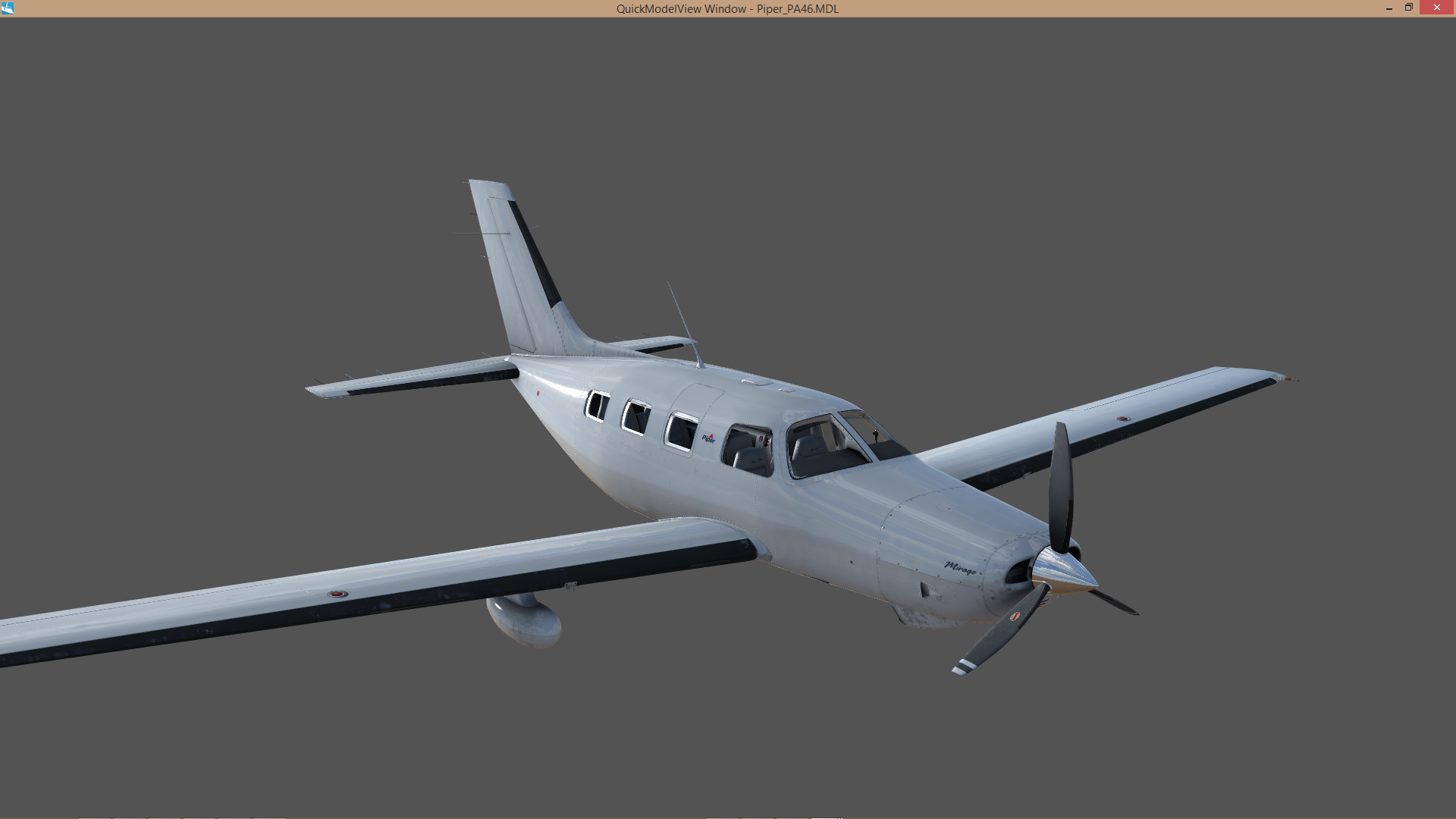
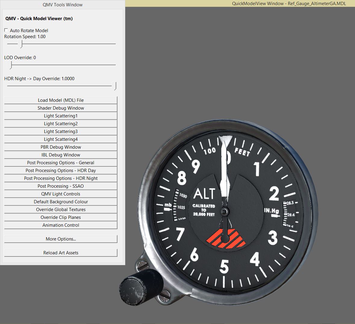
IntroductionThis document intends to convey new features and techniquesbeing developed for Flight Sim World to those familiarwith previous titles built with this engine. Some of the ideas laid out here are preliminary and subjectto change. All important changes will be clearly indicated in the relevantsections. Feedback from external teams utilising this document is both appreciated andencouraged. Software Development Kit 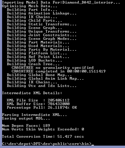 Command-line ToolsXToMDL hasbeen significantly improved in FSW. The previous version of the programconverted mesh data into an intermediate XML format before compiling it intobinary MDL format. While XToMDL still does have an intermediate step, this is now a binary format, granting a substantive increase to the program’soverall performance. Another significant improvement, is to the index/vertexbuffer size. Titles built on prior versions of this engine were limited to 16-bit index/vertex buffers whereas FSW supportsboth 16-bit and 32-bit index/vertex buffers. This means that aircraft greaterthan 65,000 vertices in size can be implemented in FSW, unlike in previous titles built with this engine. The way in which a user interacts with XToMDL has notchanged. The output text generated during and after MDL compilation has changedhowever. More information is now provided to assist in troubleshooting problemsand identifying bugs. Quick Model ViewQuick Model View (QMV) is a useful tool used in-house to view modelsin FSW quickly. A good analogue is Marmoset Toolbag, a popular real-time engine. Loading-up FSW to view small changes can be time costly - QMV aims to mitigate this. QMV is presently unavailable to the general public, but this may change in future updates. Modelling PracticesIn this section we examine how modelling practices havechanged for FSW. Vertex Count LimitIn titles built on prior versions of this engine, aircraft were limited to 65,000 vertices. This isnot the case in FSW. See Command-line Tools for more information. Edge Flow & DistributionGiven that FSW is a modern simulator, and the 65,000 vertexlimit has been lifted, a FSW aircraft should be modelled in greater detail thanthat built with a prior version of this engine. 350,000 vertices is not unreasonable for a light aircraft,provided it is modelled efficiently. This means care should be given to usevertices effectively with the artist being mindful of the edge-loopdistribution. The following ground rules should be followed in most cases:
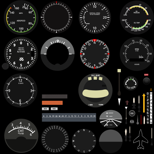
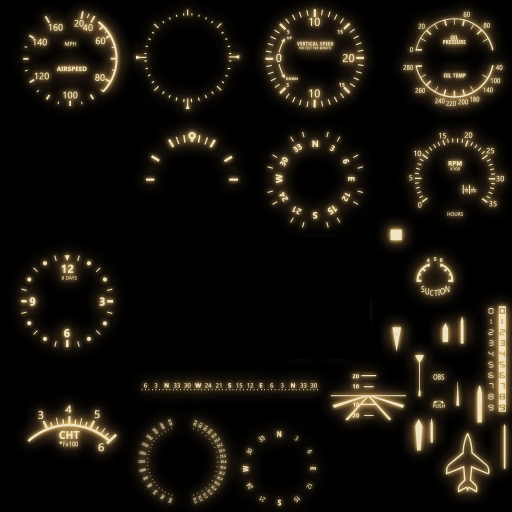
Smoothing Groups & Support Edges A box with 6faces (and smoothing groups separating each edge) is inadequate for realisticshading. Instead, a better result is achieved by applying achamfer/bevel to each edge such that 18 faces exist in total. While in formercase, a box with 6 faces employed multiple smoothing groups; in the lattercase, only 1 smoothing group is necessary. This principle is transferable toall shapes where a sharp edge is present. See Smoothing Group Theory for more information. Importance of Chamfered Edges Edges with a perfect 90 degree incidence are seldom found in the real world. Applying a small chamfer to an edge, no matter how insignificant, can vastly improve the way a surface appears in-engine. In short, chamfers soften edges and add realism. In the below images, both objects are being lit by the same light source and share the same material properties. The only difference is that the object on the left has chamfered edges. Note how the edges are more defined and how shading and specularity are better represented on the chamfered object. 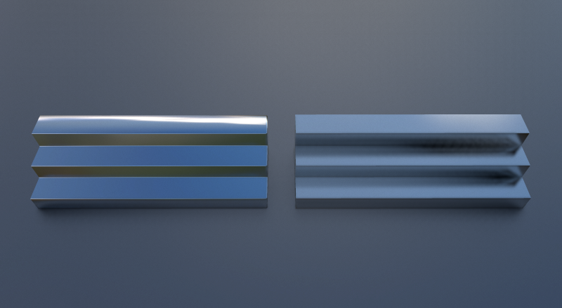 Character ScaleFSW uses a character swapping system in which exposed flesh and clothing are treated as separate, interchangeable entities. This necessitates that character size is standardised, and a single biped rig is used. FSW's character rig stands at 1.75 metres tall. It is important that aircraft are modelled to take into account FSW character size. See Characters for more information. Gauges & Dynamic TexturesEvery aspect of an aircraft should employ use ofPhysically-Based Rendering (PBR), including its gauges. The same PBR principalsapply to texturing gauges as elsewhere. In titles built on prior versions of this engine, gauges are unlit and use two textures that areswapped between depending upon time-of-day. This is a very unrealisticrendering approach by modern standards. FSW frees itself from this limitationby using an additive approach. A light source adds light to a scene. Emissive maps describe the light produced by a material and can also be thought of as additive. FSW expects an entire PBR texture set for gauges, including an emissive map, which is used during night.
Figure 18: Example of an albedo map and corresponding emissive map. Assigning MaterialsDDS Handling in Photoshop®
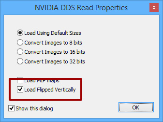
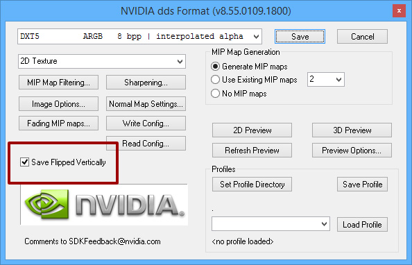
DDS Handling in 3ds Max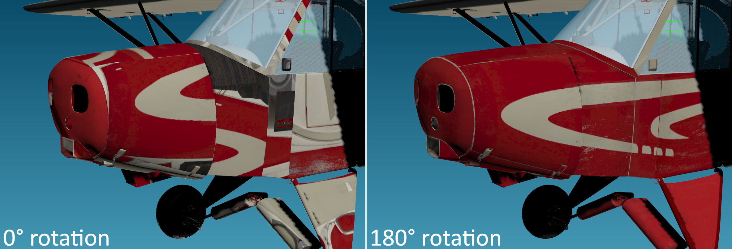 3ds Max will load DDS files as they are saved, in an inverted state. This will cause them to appear incorrectly in the viewport windows. To correctly display them:
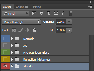
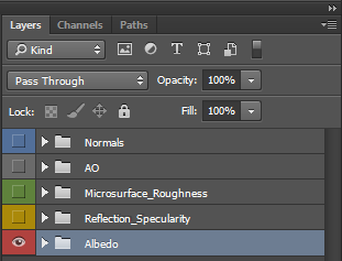
Propeller ShadowingSpinning propellers look best in FSW when not receiving shadows.As the same laws of physics apply to propellers as other objects, they would receive shadows in real life. However, due to the blade's curvature, combined with the speed at which they spin, and the unlikeliness of the eye to be focused at that particular distance, the resulting shadow would be imperceptible during normal flight. Shadows can be removed from a mesh in the material editor by ticking 'Don't receive shadow' in 'Enhanced Parameters,' seen below. It is recommended that this option is restricted to spinning propellers only. A slow spinning or stationary 3D propeller should receive shadowing. 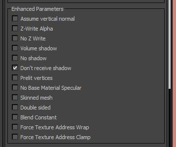 Texture FormattingHere, we examine the conventions used to create engine-readytextures. The image files FSW expects are stated in the Physically-Based Rendering: Application section. Source FilesIt is recommendedthat one Photoshop® (PSD) file is created per texture set — with each individualtexture residing within its own folder. Colour coding (as illustrated below)will help the artist quickly identify a given folder.
Figure 19:One folder is allocated to each texture type Engine FilesEach texture type has its own suffix used in the filename ofthe texture. This is not an engine requirement but lends consistency to textureorganisation. The suffixes are stated in the Physically-Based Rendering: Application section. In most cases the DXT1 and DXT5 encoding formats are bestfor engine textures. However, Dovetail Games has found that these encodingformats have bit-depths unsuitable for soft gradients. Although more expensive,we recommend using the 8.8.8.8 (ARGB) format for combined maps that featureaircraft interiors; this will preserve the soft gradients in ambient occlusionmaps. The following table can used as a quick reference forestablishing texture formatting:
Model FormattingAs with the last section, this section covers theconventions used for making game-ready content. This time: the actual models. Source Files3ds Max (MAX) and Marmoset Toolbag (TBSCENE) files may beconsidered as source files. Textures and corresponding TBSCENE files must be storedwithin the same directory. Otherwise the textures will not load correctly onother artists’ machines. Engine FilesIn the process of making the final engine model files (MDL),an intermediate file is first generated. This file (X) can be produced directlyin 3ds Max 2016 via the File → Export dialogue. The X file is then fed intoXToMDL in order to create an engine-ready MDL file. XToMDL does not have an interface. It is invoked via thecommand-line and controlled by arguments that are passed to it. The firstargument passed should always be a path to the X file being converted. The following table lists the other arguments that should beincluded for compiling an aircraft into MDL format:
See Command-line Tools for more information on XToMDL. |
Aircraft >