In addition to this, exposed skin (i.e. heads, and hands), are treated seperately to
clothing, allowing any combination of the two to form a character.
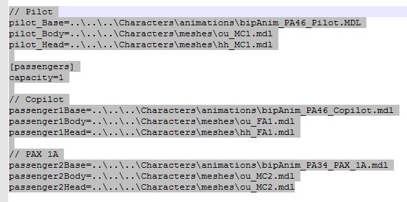
Default characters can be specified within an aircraft's model.cfg file as illustrated
in the image below.
The number of passengers present in the
model.cfg file must be specified using the tag
[passengers] followed by
capacity=n on the next line, where
n is an integer value.
Animations can either be generic across all aircraft and seats, or specific to a particular
seat of a particular aircraft.
Tail Numbers
The tail number of an aircraft corresponds to its unique identifier. It can be
painted on various parts of the aircraft.
Because tail numbers can be dynamically assigned at run-time, they should not be
baked directly into textures. Instead, artists should reference a dynamic texture
which the engine creates at run-time (rendered via a render target). By convention,
all dynamic texture names must start with $ and the name of the tail number texture
is $registration.
There are a few lines to set in the aircraft.cfg file in order to get the tail
number working properly. Note the following key/pair values have to be set for
each variant of the aircraft (fltsim.0, fltsim.1, …):
- atc_id: This is the default registration of the player’s aircraft. Example: G-BRGI
for a general aviation aircraft in the UK.
- atc_id_font: This is the font name used for rendering the tail number. The font
name must correspond to an entry in Fonts/fonts.json file. Example: “Arial
Big”.
- atc_id_color: This is the colour which will be used to render the tail number.
This is a hexadecimal number using ARGB format. Example: 0xFF00FF00 for pure
green.
- atc_id_render_target_width: This is the width of the render target which will
be created to render the tail number. Note that AI aircraft will have this
size divided by 2 (e.g. 512)
Real-time Raindrop Effect (and Refraction)
FSW features a brand new real-time raindrop solution. It calculates and renders
falling raindrops, taking into account forces such as wind, acceleration, and
gravity. Below, we explore how to setup an aircraft to use the new system.
Raindrops are generated as 2D texels in a compute shader. They assume the U axis
points along the world XZ-plane, and the V axis is aligned with the world Y
(up) axis. Any other UV configuration will lead to odd raindrop behaviour,
including inaccurate travel paths. Distances between UV points should be as
proportionate as possible to prevent raindrops changing size during their lifetime.
This makes a cylindrical unwrap the most appropriate UV unwrap solution. Some
cleanup work will be necessary to ensure the cylindrical unwrap is proportionate
on the V axis.
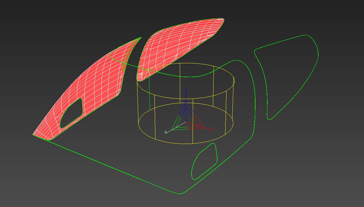 It's essential the V axis is aligned to the world Y (up) axis as stated previously.
Otherwise, the compute shader won't have a correct concept of up-and-down,
meaning raindrops will move along the wrong axes in-engine. Further, UV projection
should be cast from the perspective of a pilot looking out through the windows.
If using a cylindrical unwrap, for example, the projection cylinder should
not envelope the window geometry and cast inward; rather, it should reside
within the window geometry and cast outward.
It's essential the V axis is aligned to the world Y (up) axis as stated previously.
Otherwise, the compute shader won't have a correct concept of up-and-down,
meaning raindrops will move along the wrong axes in-engine. Further, UV projection
should be cast from the perspective of a pilot looking out through the windows.
If using a cylindrical unwrap, for example, the projection cylinder should
not envelope the window geometry and cast inward; rather, it should reside
within the window geometry and cast outward.
The next step involves generating an object-space normal map (OSN) for the windshield
geometry. Any normal map baking program with the option to use a model/object
space projection can be used for this (such as xNormal or 3DS Max's
Render to Texture feature). A configuration file for the preferred in-house
solution, xNormal, can be found here:
FSW_OSN.xml
If using a program other than xNormal, it is essential to ensure swizzling, axis
polarity and/or handedness matches xNormal's default output.
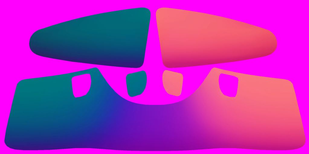
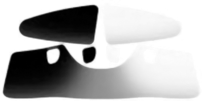
If results in-engine are inconsistent with expectations, looking at individual colour
channels of the OSN will help diagnose the problem. Each colour channel represents
a pixel's normal direction in
World-Space along a particular axis
. The image below, for example, depicts an OSN map's Red channel (i.e.
it's X-axis). The white pixels on the right represent normals pointing positively
along the X-axis, and inversely, the black pixels on the left represent normals
pointing negatively along the X-axis. The grey pixels in the centre have little-to-no
magnitude along the X-axis as they represent the front of the windshield where
normals point positively along the Z-axis.
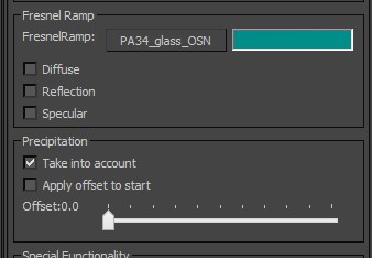
The object-space normal map should be stored in the aircraft texture folder with
the suffix
_glass_OSN.dds The texture should then be plugged into the material's FresnelRamp
slot, and in the precipitation section,
Take into account should be checked. In the latest SDK version, the required
setup is slightly different. Please refer to:
3DS Max Plug-in: PBR Material.
One final step is to ensure raindrops die at window edges by adding an
Exclusion map to the alpha channel of the OSN map. White permits the existence
of a raindrop, and black kills a raindrop upon touching it.
This same functionality can additionally be used to
simulate refraction for other effects, such as shattered glass.
For this, the material should be configured in the same way as glass for windscreen
raindrops. FSW will use the the material's normal map to determine the screen
lookup position. Raindrops are supported on refractive materials as per normal.
At present, a few limitations apply:
-
refraction is only available when viewing the interior of an aircraft
- materials with alpha will not be visible through refractive materials
Also note that certain material properties behave differently:
-
Albedo - is used to tint/attenuate the light which the material
is refracting - i.e. white will allow light through unaffected, while solid
red would permit only red light
-
(Albedo) Alpha - is used to determine how much light is diffusely-reflected
rather than transmitted/refracted - 1 = fully opaque, 0 = fully refractive
Point Lights
FSW features point-lights with quadratic falloff. They are markedly more realistic
than point-lights in previous titles built with this engine.
Currently, only four point-lights can be placed within a single aircraft, although
this limit will eventually be removed. It is recommended they are used to simulate
cockpit floodlights and dome-lights.
Within a
.fx file, a point light's attributes are defined by the following:
[ParticleAttributes.0]
- Color Start, Color End - these represent the colour/intensity of the light
- Light Range - distance at which the light is cut off (to prevent light passing
through doors/other geometry)
- Light Range Fade - distance over which the above cut-off if blurred over, to
make it less perceivable
Ambient Point Lights
In previous titles built with this engine, an ambient
colour is added across the board to ensure no region is 'too dark.' This doesn't
make sense in a modern HDR lighting pipeline where brightness ratios should be
truly representative of real-life counterparts. However, without adaptive luminescence
(a feature planned for the future), having extremely dark areas can be destructive
to the simulation experience; this is particularly evident on the gauge fascias
cast under shadow.
To mitigate this, ambient point lights can be used to simulate ambient lighting.
This is preferential to the previous approach, as it only applies to the local
area of the point light, meaning lighting elsewhere in the aircraft is undisturbed.
Applying ambient points light is entirely option and should be avoided where unnecessary
due to the performance cost.
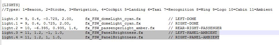
Ambient point lights are added to the aircraft in the 'aircraft.cfg' file within
the
[LIGHTS] section. They should be assigned to lighting circuit 11, which has
been newly added to FSW for this express purpose.
Additive-Specular Materials
Traditionally a material which has a very low alpha value would be invisible, and
would reflect no specular light. However, many real-world transparent materials
do not behave in this way, instead reflecting large amounts of specular light.
For example, sunlight reflecting on glass.
To simulate this effect, FSW can allow translucent materials to reflect all specular
light, as though they were regular opaque materials. This can be enabled via
the
Blend Constant property in 3DS Max.
Note that alpha values must
slightly
exceed 0 for this effect to be visible; a value of 0 will reflect no specular light.
This behaviour allows for features such as holes cut into glass, where an alpha
value of 0 would represent the absence of the glass.
External Lighting (Bloom and Sprites)
Previous titles built with this
engine approached external lighting by using sprites to give the impression of
a bright light source shrouded in bloom. FSW uses a hybrid approach, utilising
the previous system at a distance, and true HDR bloom at mid-to-short range.
External lights should be modelled and made emissive through texture and material
setup; they will then bloom via the HDR system.
In order for a sprite to appear beyond a certain distance, two additional lines should
be added to the relevant .fx file.
Fade In Distance Start=30.0
Fade In Distance End=60.0
These parameters specify where the sprite fade transition starts and ends.
Poly-picking
In previous titles built with this engine, an entire aircraft
would be tested for mouse events. FSW has been optimised to only test explicitly
designated geometry for mouse events. This greatly reduces the CPU overhead associated
with mouse testing.
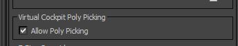
Geometry with associated mouse events should have the flag, ‘Allow Poly Picking,’
in the section, ‘Virtual Cockpit Poly Picking,’ enabled.
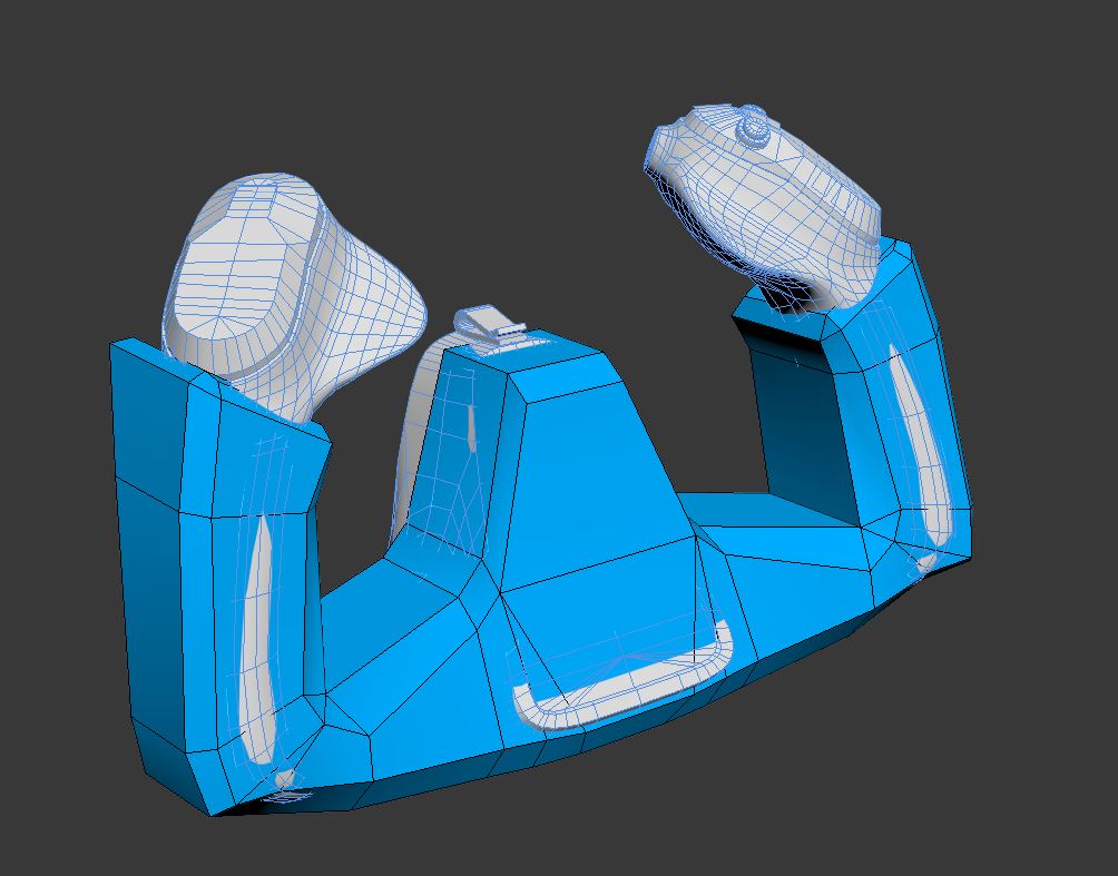
In previous titles built with this engine, it was common to tie a functionality
tag (i.e. mouserect tag) to an actual piece of rendered geometry seen by the
end-user. Because the poly-count of FSW content can be quite high, this no longer
makes sense. We suggest using a low-poly proxy mesh as illustrated below. In
testing, this approach has freed-up around 10 FPS during mouse event testing.
Generally, a dedicated poly-pickable mesh will be parented to the corresponding
rendered mesh. This helps with scene organisation, and ensures moving parts
remain interactive.
Tooltip Helpers
Helper tooltips can be applied to geometry u
sing the mouserect option of the
Attach Point Tool. The same methodology as with polypick objects applies
to helper objects. Helpers are useful for providing readouts, explanations
and information about a given object (such as a gauge) to the user when
in the cockpit.
See the
Tooltip Helpers List page for a comprehensive list of currently available
helpers.
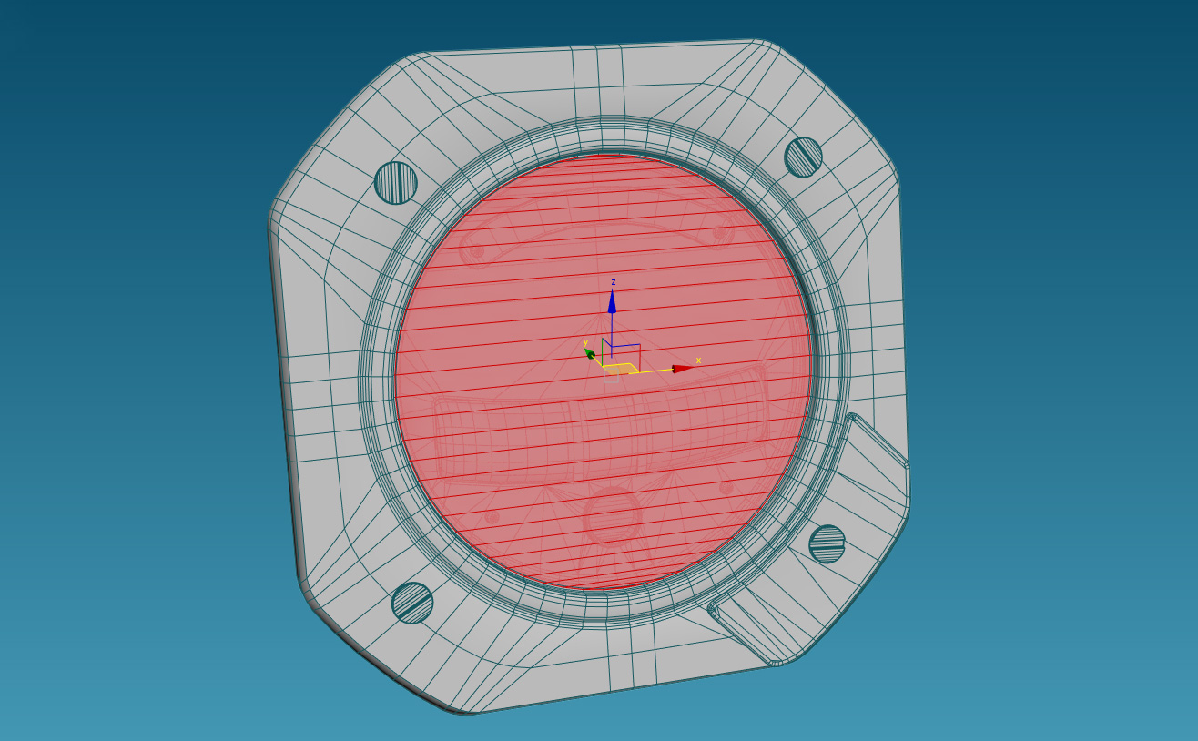
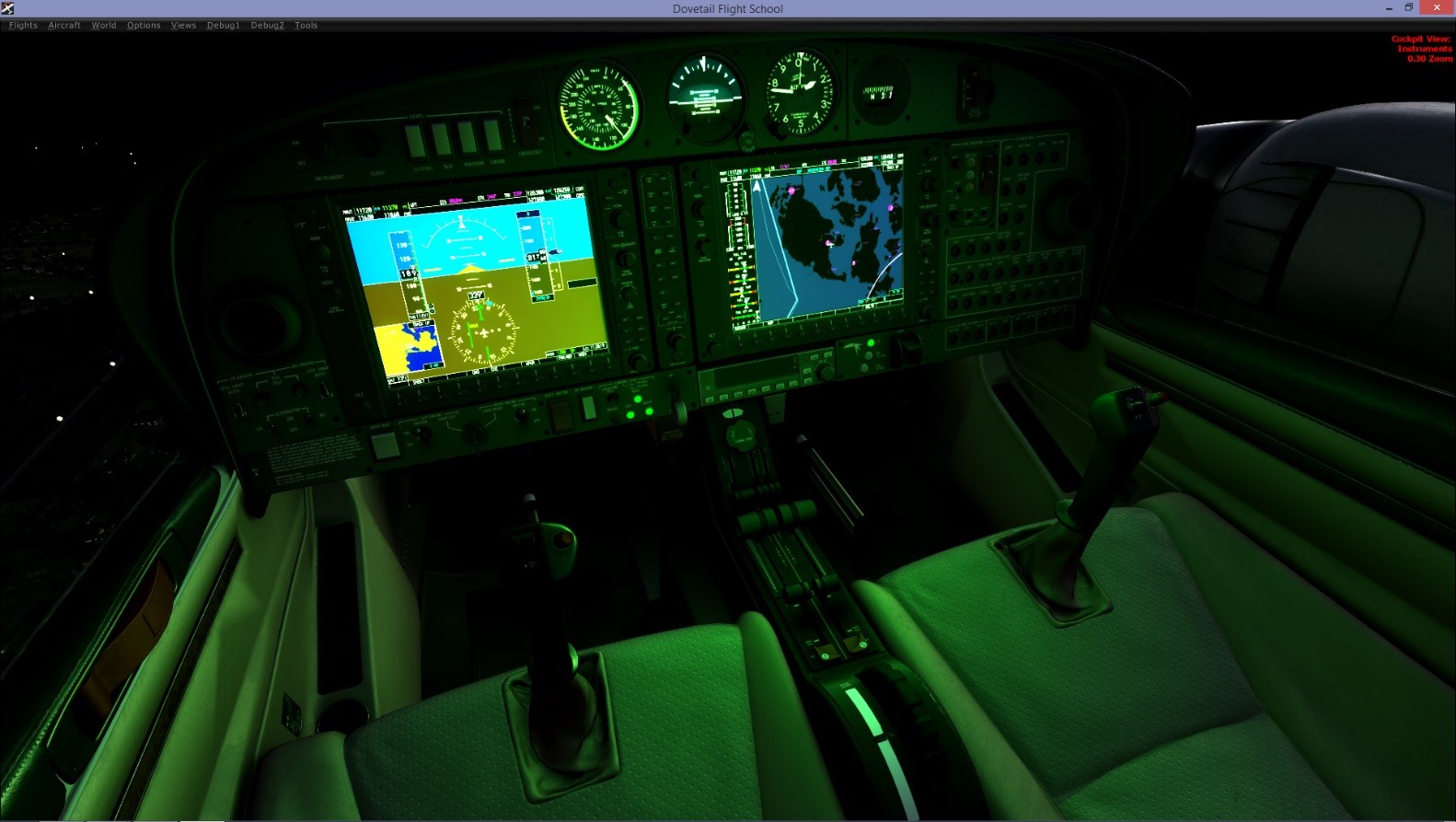
The image on the left demonstrates a helper object applied to the fascia of the
gauge. Upon mouse-over, the player is presented with a tooltip describing the
function of the gauge.
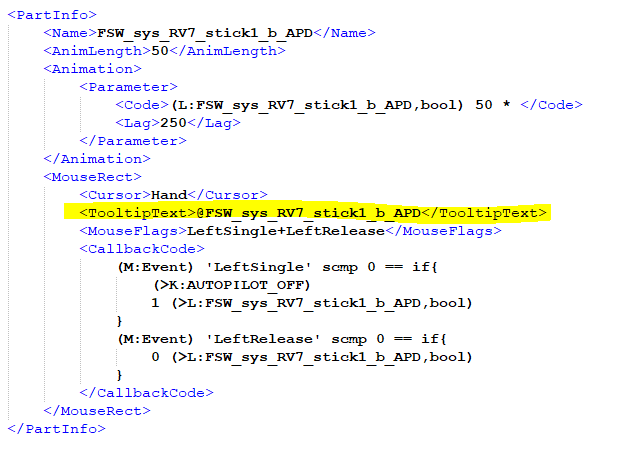
Tooltip Translation
FSW features a new system for simple tra
nslation of aircraft tooltips.
Tooltips specified in the
modeldef file can now be translated using the
TooltipText tag. If a translation string ID is used within the
TooltipText tag, this will get replaced with the appropriate string
(based on language selection) when processed in engine. Note that a @ symbol
is required at the start of the string ID. It's also possible to use gauge
code within the string which will get evaluated when the tooltip is shown
(e.g to show on/off depending on switch state).
See the images below for an example. The translation string IDs can be from
the core FSW translation set or additional translation set supplied with
the aircraft.